Reservoir owner and operator guidance: spillways
How to design, inspect, monitor and maintain impounding reservoir spillways so they are safe.
Applies to England
An impounding reservoir is an artificial lake created by building a dam across a natural stream.
You should follow this guidance if you are an owner or operator of an impounding reservoir.
To efficiently design, inspect, monitor and maintain your reservoir spillways, you should:
- understand your role and responsibilities and those of others
- be familiar with the spillway function and its different parts
- understand the impact of the spillway design and operation on the safety of the reservoir, operators, visiting public or downstream communities, environment and infrastructure
- be familiar with the potential spillway failure mechanisms
- understand the main principles and requirements for spillway inspection, monitoring and maintenance
Roles and responsibilities
The safety of impounding reservoirs depends on the joint efforts of several organisations and individuals, including:
- reservoir owners and operators
- qualified civil engineers involved in their supervision
- qualified civil engineers involved in the inspection and construction process
- designers
- contractors
- the enforcement authority
- various other organisations
The main legal duties of owners, operators and others involved in ensuring reservoir safety are outlined in the reservoirs: owner and operator requirements guidance.
Owners and operators may also have responsibilities under the Construction (Design and Management) Regulations 2015. These regulations aim to make sure the reservoir is safe to build, use and maintain.
Owners and operators have a duty of care to make sure that the spillway design and operation do not pose any unacceptable risks to:
- operators
- the public
- the environment
- infrastructure
Risks could relate to:
- unguarded deep structures
- other dangerous structures
- steep and potentially slippery surfaces
- high velocity flow of water
- erosion
- flooding
Spillway function and components
A spillway allows water to safely flow away from the reservoir during normal operation and during a flood. It should do this in a way that:
- protects the integrity of the dam
- prevents adverse safety, environmental or economic impacts
The main parts of the spillway are:
- inlet structure
- conveyance structure
- energy dissipator
- downstream channel
There are a wide variety of reservoir spillways and some are complex.
You should discuss the spillway function and its main parts with the supervising engineer or the designer for new or proposed spillways. They can help you improve your understanding of how it operates and how to inspect, monitor and maintain it.
Inlet structure
For most spillways, the inlet structure includes a weir that freely releases water. This controls the water flow within the spillway and the reservoir water level.
Weirs can have different shapes. For example, in a cross section, the weir could have an ogee (s-shaped), trapezoidal, rectangular, triangular or sharp-crested shape. In plan, the shape of the weir can vary too. The most common shapes are straight or a simple curve.
A free weir inlet structure is typically next to or over the dam (figures 1 and 2). It is often followed by an open channel ‘conveyance structure’. The conveyance structure conveys the flow of water from the inlet structure and discharges it downstream of the dam.
When the inlet structure is built over an embankment, it normally, but not always, extends into the impermeable clay core through a cut-off. This is a wall built into the ground to control seepage.
If the water depth is shallow upstream of the inlet structure, an approach channel is sometimes built in front of the weir. This manages the flow to reduce the risk of erosion and blockage of the weir.

Figure 1: cross section of a free weir inlet structure
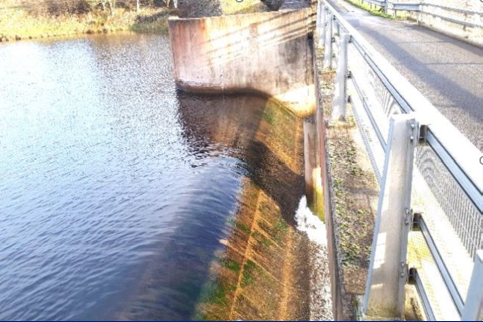
Figure 2: side view of a free weir inlet structure (Source: V. Pavlov)
Some weirs have a non-linear shape in plan. They feature folds that increase the weir length where space is limited. These are called labyrinth weirs (figure 3) or piano-key weirs (figure 4).
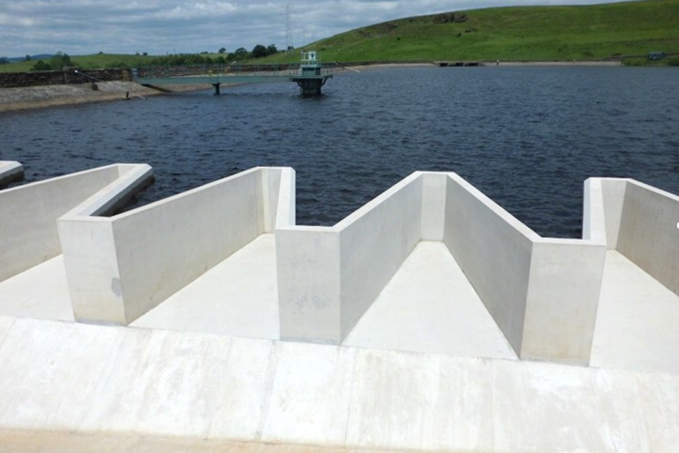
Figure 3: labyrinth weir (Source: V. Pavlov)
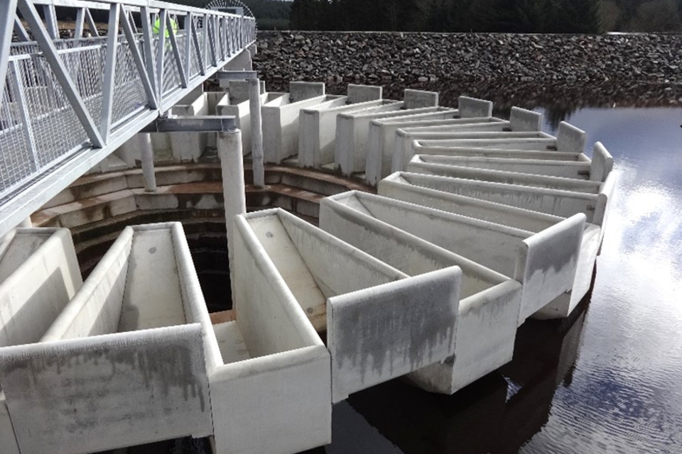
Figure 4: piano key weir (Source: J. Ackers)
In some cases, the inlet weir shape is circular in plan. Circular weirs are typically provided at the inlet to shaft spillways. Shaft spillways are enclosed conveyance structures (such as a pipe). They are normally, but not always, constructed in natural ground (abutment) beneath or around the dam (figures 5 and 6) in a tunnel.

Figure 5: cross section of a circular weir and enclosed conveyance structure in natural ground
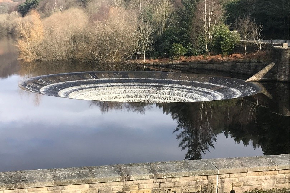
Figure 6: side view of circular weir (Source: P. Farnell)
Submerged inlet structures are sometimes used to control the spillway flow and reservoir water level. The control is either defined by the geometry of the opening or by the capacity of the downstream conveyance structure.
One specific type of submerged inlet structure is the siphon. Unlike other inlet structures, it suddenly increases the flow of water as the siphon primes (starts running under pressure).
In some reservoirs, the spillway flow and reservoir water level are controlled by:
- permanent gated structures
- temporary collapsible gates (tipping gates)
- sacrificial embankments, sometimes referred to as earth-fill fuse plugs
At concrete dams, the inlet weir structure and conveyance structure can form part of the dam (with water flowing over it).
Conveyance structure
The conveyance structure conveys the flow of water from the inlet structure and discharges it downstream of the dam.
It could take the form of an open channel (a chute) or a conduit (pipe, tunnel or culvert). In a conduit, water can either flow part full (free surface) or full (under pressure).
There are 4 main types of open channel conveyance structures.
A smooth reinforced concrete chute maximises the capacity of the channel. It reduces the channel depth and minimises flow turbulence (figure 7).
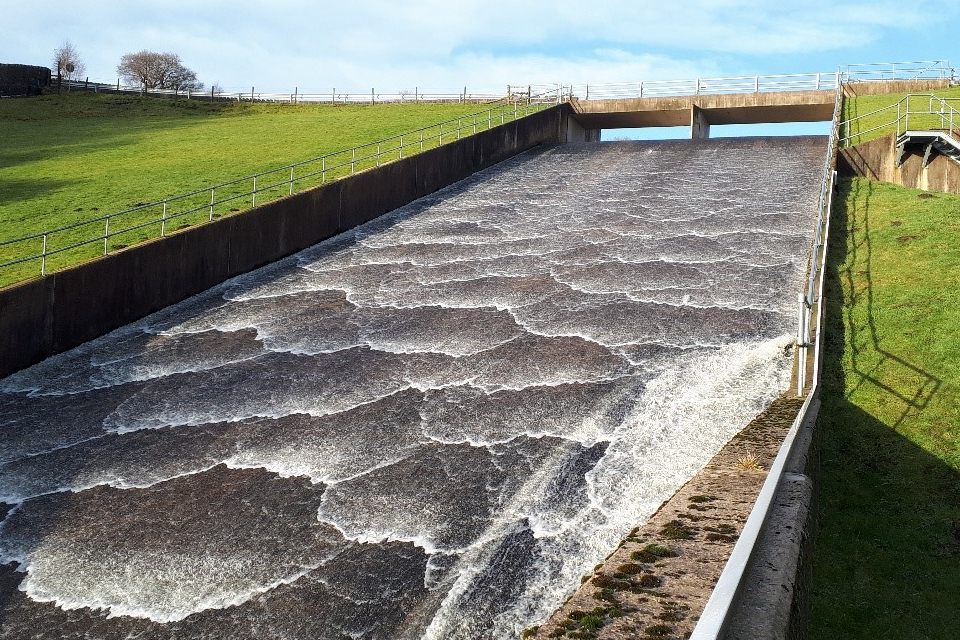
Figure 7: smooth reinforced concrete chute (Source: V. Pavlov)
A stepped chute dissipates some of the energy of the flow as it travels along the chute (figure 8). It reduces the need for further energy dissipation at its base.
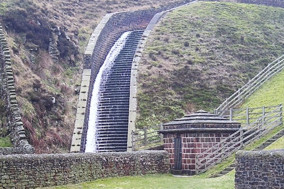
Figure 8: stepped masonry chute (Source: United Utilities)
A baffled chute has large blocks protruding from the surface that dissipate all or most of the energy of the flow (figure 9). It reduces or eliminates the need for further energy dissipation at its base.
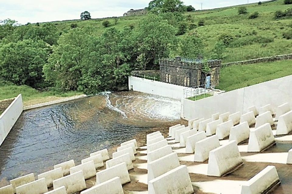
Figure 9: baffled chute (Source: V. Pavlov)
A natural ground channel, with or without surface protection, is typically used for spillways that are not used much and where flow velocities are low. Such spillways are typically used in flood storage reservoirs or as auxiliary spillways. Some natural ground channels are protected with reinforced grass. The grass chute is reinforced using geotextile or concrete to enhance erosion resistance (figure 10).
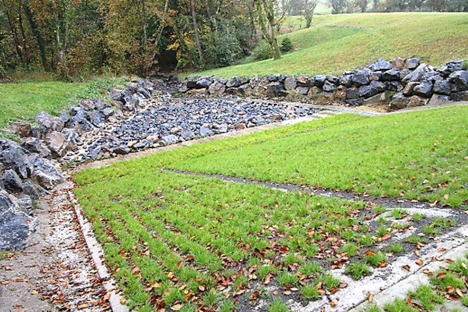
Figure 10: reinforced grass chute (Source: J. Hinks)
Pipes, tunnels and culverts convey the flow from shaft spillways (figure 11).
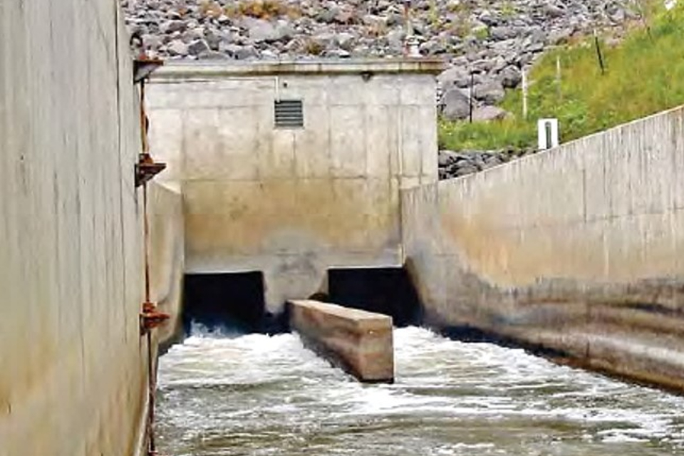
Figure 11: outlet of a culvert conveyance structure (Source: Federal Emergency Management Agency, USA)
Energy dissipation structure
The energy dissipation structure is at the base or end of the conveyance structure. It reduces the kinetic energy of the spillway flow to prevent excessive erosion downstream of the conveyance structure. Erosion could:
- undermine the energy dissipator or the entire spillway
- undercut the dam causing it to fail
- cause unacceptable erosion of the watercourse or natural ground receiving the water
A hydraulic jump stilling basin is a commonly used energy dissipator in the UK.
A hydraulic jump is a rapid transition between the high velocity flow at the base of the spillway and the low velocity flow within the stilling basin. A stilling basin reduces the kinetic energy of the spillway flow by creating turbulence within the hydraulic jump.
The stilling basin is typically a horizontal channel at the base of the spillway that may end with a sill (wall) to create a pond (figure 12).

Figure 12: view from the base of a spillway showing a hydraulic jump stilling basin during operation (Source: V. Pavlov)
Sometimes extra turbulence is generated using baffle blocks within the stilling basin. They are located at the beginning and within the stilling basin. Having baffle blocks reduces the length of the hydraulic jump (figures 13 and 14).

Figure 13: cross section of a hydraulic jump stilling basin with baffle blocks

Figure 14: side view of a hydraulic jump stilling basin with baffle blocks (Source: United Utilities)
Another type of energy dissipation structure used within open channel conveyance structures is the ‘ski jump and plunge pool’. This is less typical in the UK.
Sometimes referred to as a ‘roller bucket, it has a vertical curve at the end of the channel, forming a ‘bucket’ which forces the flow to jump out of it (figure 15).

Figure 15: ski jump and plunge pool energy dissipator (Source: C. Goff)
It dissipates energy by:
- friction through the bucket
- allowing the jet of water to interact with the air
- water cushioning (reduction of the energy of the water jet) within the plunge pool which reduces the impact of the jet on the riverbed
It is normally used to direct high velocity flow away from the dam where potential erosion would not endanger it. It could also be used where the downstream water is too deep to form a good hydraulic jump.
Stilling basins are also often used where large diameter pipes, tunnels and culverts are used as conveyance structures.
For smaller pipes, other types of energy dissipators such as the United States Bureau of Reclamation (USBR) impact-type energy dissipators or stilling wells are sometimes used. They dissipate energy through jet impact or combined jet impact and water cushioning.
The impact-type energy dissipator has a baffle wall in the spillway outlet. There is an opening beneath the wall where the flow exits. The jet impacts against the wall to dissipate the flow energy (figure 16).

Figure 16: USBR impact type energy dissipator (Source: Technical Manual: Outlet Works Energy Dissipators, 2010, Federal Emergency Management Agency, USA)
The stilling well energy dissipator has a chamber that fills with water during spillway operation. It dissipates the flow energy by cushioning the water (figure 17).

Figure 17: stilling well energy dissipator (Source: Technical Manual: Outlet Works Energy Dissipators, 2010, Federal Emergency Management Agency, USA)
Downstream channel
When the spillway flow leaves the energy dissipator it usually still has some residual turbulence. This could erode the receiving watercourse.
You can resolve this by ensuring flows from the spillway are appropriately directed into the watercourse. You can also train flows by using extra protection in a transitional length of watercourse (downstream channel). For example, you could use rip-rap rock armour (selected large stone material) to line the channel.
Spillway design impacts
The design of new spillways, or changes to existing spillways, could have an impact on the safety of the dam, operators, public, environment or infrastructure.
Dam safety impact
To protect the integrity of the dam, the spillway design should:
- keep the flow in the spillway channel
- prevent overflowing of the dam
- prevent or minimise overtopping
Dam overflowing is when the still water in the reservoir exceeds the dam crest level.
Overtopping is when wave or splash water surges over the top of the dam or the spillway side walls.
You can prevent overflowing by providing an adequate allowance for uncertainties, for example in the design and modelling, to the top of the:
- impermeable embankment element (such as a clay core)
- embankment crest
- conveyance structure side walls
- energy dissipator side walls
You can prevent or minimise overtopping by providing sufficient distance between the design still water level and the dam crest (freeboard).
The spillway structure must be robust enough to resist all static and dynamic loads without failing during its entire design life.
Health and safety impacts
Spillway structures could create health and safety hazards to operators or the public.
This may be due to the presence of:
- deep channels creating a fall from height hazard
- steep slopes, creating a slip hazard
- enclosed conduits, creating a hazard of becoming trapped and a drowning hazard
- fast flow creating a drowning hazard
You should manage all hazards and risks during the design and construction of the reservoir spillway.
You should provide operators with safe access to all critical parts of the spillway and to equipment such as spillway gates or valves. Severe weather conditions or normal operation of the spillway structure should not impede access.
If people use the reservoir for recreational activities, such as walking, boating or swimming, there is a likelihood of them falling into the spillway. Where necessary, you should provide suitable safety barriers or grilles to stop public access. The barriers and grilles should not restrict the operation of the spillway.
Environmental impact
The spillway design could have a negative environmental impact on the downstream water course. This could be due to:
- fast-flowing water and high turbulence from the spillway which erodes the riverbed and banks
- preventing sediments and floating debris passing downstream (they contribute to the ecological health of the river, for example, by providing shelter and food for wildlife)
- deteriorating the conditions for fish migration
Impact on downstream communities and structures
Changing the level or increasing the size of a spillway or adding another one can increase the frequency or magnitude of flows leaving the reservoir. This could increase the risk of flooding to downstream communities and infrastructure.
Water leaving the spillway at high velocity can cause erosion and undermine downstream structures. It can also move eroded material to locations where it could block bridges or culverts which may further increase the risk of flooding.
You must carefully consider these risks. You may also need to get permits or consents for the work.
Spillway failure mechanisms
The main risks to dam safety posed by reservoir spillways, which might otherwise have sufficient capacity, are:
- the inlet structure being blocked by floating debris
- the conveyance structure or energy dissipator becoming unstable or failing structurally
Blockage of the spillway inlet structure by floating debris
The inlet structure could become blocked by floating debris (figure 18) which could lead to a loss of some or all of the spillway capacity.
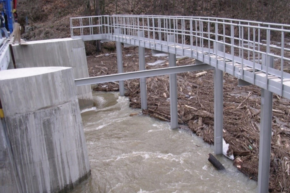
Figure 18: blocked inlet structure by floating debris (Source: Bulletin 176, Blockage of reservoir outlet structures by floating debris, 2021, International Commission on Large Dams)
This could cause water to go over the top of the dam (overflowing) or increase overtopping as the freeboard reduces.
The likelihood of a blockage by floating debris depends on:
- the nature of the reservoir catchment and margins
- whether debris can be transported to the inlet structure
- the width and height of the inlet structure relative to the floating debris
- flow velocity and depth at the approach to the weir
- the type of weir
- whether the inlet to the weir has a screen or allows for safe and timely removal of the debris
The designer of a new spillway should assess the risk of a blockage as part of the design process. They should also assess how to access the spillway and remove debris. This will enable the owner to safely clear the spillway during normal and emergency operation and maintenance activities.
During an inspection of an existing spillway, the inspecting engineer will assess the risk of a blockage. They will then establish whether the spillway inlet can perform adequately during a flood. If it cannot, the inspecting engineer may recommend measures to prevent a blockage.
Owners and operators must also think about blockages as part of their routine inspections. This might include taking preventative measures such as removing debris upstream of the inlet or managing trees along the reservoir margins.
Structural or stability failure of the spillway conveyance structure or energy dissipator
The most common reasons for open channel conveyance structures and energy dissipators to fail relate to:
- the effects of overflowing and overtopping
- downstream erosion
- uplift
- collapse
- structural damage (such as stone dislodgement or erosion of reinforced grass)
Spillway overflowing and overtopping occurs when the walls of the conveyance structure or energy dissipator are not tall enough to contain the maximum flow depth. This may purely be due to the spillway being too small but may also include the effects of:
- air bulking - increased water depth due to the presence of entrained air
- shock waves – rising surface of the high velocity flow at abrupt changes of flow direction or channel shape
- turbulence
- spraying
- splashing
Overflowing and overtopping has the potential to start surface erosion which could progress in depth and cause either:
- a slip failure of the embankment dam above
- loss of foundation and side support to the spillway walls leading to their structural failure (figure 19 and 20)

Figure 19: cross section of a spillway during overtopping
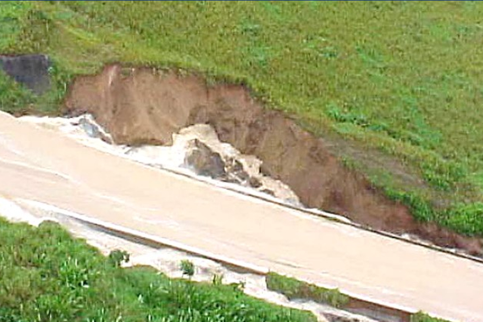
Figure 20: side view of a spillway during overtopping (Source: Best Practices in Dam and Levee Safety Risk Analysis, Chapter F-2, 2019, United States Bureau of Reclamation and United States Army Corps of Engineers)
Erosion can occur downstream of the energy dissipation structure if the flow energy is not reduced enough. This could also happen if the transition into the watercourse is not adequately protected. If the structure is not ‘keyed’ (does not penetrate) into competent ground, the erosion could undermine the spillway and cause it to fail (figures 21 and 22). The erosion could also progress upstream and endanger the dam.

Figure 21: cross section of spillway structure that has lost support and collapsed due to erosion

Figure 22: side view of a spillway structure that has lost support and collapsed due to erosion (Source: Guidance for the Design and Maintenance of Stepped Masonry Spillways, 2010, Environment Agency)
Failure of the conveyance structure or energy dissipator could expose foundation materials to fast flows. This could lead to rapid erosion of adjacent or supporting embankment dams.
Not having a drainage system or maintaining it could cause uplift pressures (vertical water pressures) that exceed the design limits of the structure. The increased uplift could cause vertical movement (stability failure), opening of joints, or structural failure of the spillway base slabs (figures 23 and 24).

Figure 23: cross section of a spillway structure showing uplift failure of the spillway base slab

Figure 24: side view of a spillway structure showing uplift failure of the spillway base slab (Source: V. Pavlov)
The spillway structure could collapse into a void caused by internal erosion of the foundation material (figures 25 and 26). Internal erosion could be caused by lack of drainage, inadequate drainage capacity, blockage or damage to the drainage system or lack of filters.

Figure 25: cross section of a spillway structure with foundation erosion showing failure of the spillway base slab due to loss of support and collapse

Figure 26: side view of a spillway structure with foundation erosion showing failure of the spillway base slab due to loss of support and collapse (Source: Toddbrook Reservoir Independent Review Report, 2020, Environment Agency)
Stepped masonry spillways are prone to stone dislodgement. This could be due to:
- negative pressures (vacuum) developing downstream of the steps
- settlement
- cracking
- masonry and mortar deterioration caused by seepage of water and made worse by vegetation growing in joints
Poor drainage or stone dislodgement can cause the masonry spillway side walls to move, lean or collapse (stability failure).
Reinforced grass spillways are prone to failure due to erosion. Things that affect erosion include:
- poor grass cover (poorly maintained, low density, irregular growth, weeds, woody vegetation)
- mechanical or UV damage to the reinforcement, low spots, changes in spillway slope, cracks, holes, shrubs, trees and structures concentrating the flow
- lack of attention during construction, such as not overlapping adjacent panels, not pinning them securely or not providing suitable topsoil cover
- poor detailing of the reinforced grass spillway at the dam crest, mitres and toe and where they are joined to structures
These spillways can also be prone to sliding within the soil mass of underlying embankments. This happens when the subsoil has high permeability and is saturated by prolonged overflowing events.
See more detailed guidance on spillway failure mechanisms.
Routine inspections by operators
Operators should carry out routine inspections.
Routine inspections are normally done once or twice a week or daily if a specific risk justifies it.
Your supervising engineer will advise you on the scope and frequency of the routine inspections. The supervising engineer will consider the following when giving advice:
- the nature and condition of the dam and its spillway
- its operating regime
- the risk posed by the reservoir to the downstream community and structures
During the routine inspection you should:
- check whether the spillway operates as intended (clear and unobstructed)
- check for damage or deterioration of the condition of the structure and its surroundings that has or may affect its safety
The routine inspection will allow you to:
- take actions to clear obstruction such as floating debris
- take emergency actions to reduce the flow over the spillway, for example, by operating the draw-down facility or diverting the inflow into the by-wash channel
- raise issues that need immediate attention or further investigation by the supervising engineer
You should keep records of your routine inspections, including photographic evidence.
Detailed inspections by operators
Depending on the type of spillway, you can check different spillway features and conditions in more detail to:
- investigate any non-urgent issues raised during the routine visual inspections such as local erosion downstream of the energy dissipation structure
- identify any extra maintenance such as clearing vegetation, repointing or replacing joints
You should keep records of your detailed inspections, including photographic evidence.
You may wish to delegate this task to the supervising engineer. Doing this will depend on the nature of their appointment and the frequency of their visits.
Reinforced concrete spillways
For reinforced concrete spillways, you could check for the following features and conditions. Please note these activities are not exhaustive.
Rising steps at joints or cracks happen where the level of the downstream slab (in the direction of flow) is higher than the level of the upstream slab (figure 27). Rising steps create stagnation pressures in joints and cracks that may increase uplift pressure if a water barrier (water-stop) is not present or damaged. Stagnation pressures happen when a high velocity flow goes down due to the rising step.
A rising step could form if there is:
- significant movement at dowel bars (short steel bars that provide a mechanical vertical connection between slabs without restricting horizontal joint movement)
- concrete spalling (braking of concrete down into small flakes) upstream of cracks

Figure 27: effect of rising steps on uplift pressure
Drop steps at joints could form due to excessive uplift pressure and in some cases could cause turbulence and damage due to vacuum.
Concrete cracking can happen at critical locations such as:
- in the middle of the spillway slab
- near the sidewalls, doweled joints and bridge piers
- around baffle blocks or end sills
Excessive cracking could lead to corrosion of reinforcement.
Uneven opening and closure of expansion joints could create excessive compressive stresses at points of contact and cause damage to water-stops (barriers to leakage).
Concrete spalling and delamination could occur near joints and may lead to stagnation pressures and increased uplift.
Exposed reinforcements will cause the reinforcement to corrode and reduce the strength of the structure.
Visual hogging or sagging deformation of spillway slabs would normally be associated with large structural cracks and could lead to corrosion of reinforcement and structural failure.
The side wall could deflect from the vertical. This could happen because of:
- frost heave (soil expansion due to freezing of groundwater)
- excessive surcharge placed behind side walls
- external pressure from vegetation roots
- loss of side support due to external erosion or dessication
Deflection could lead to overturning or structural failure of the side wall. It may also obstruct the high velocity flow causing turbulence and possible overtopping of the spillway side walls.
Damaged or removed expansion joint sealants and filler boards could cause material or vegetation roots to fill the gap. This would compromise either the effectiveness of the expansion joint or damage the water-stop or both.
Vegetation growth in movement joints or cracks could lead to:
- crack growth and corrosion of reinforcement
- damage to the water-stop and reduced effectiveness of the movement joint
- loss of the expansion joint sealant and filler
Masonry spillways
For masonry spillways, you could check for the following features and conditions. Please note these activities are not exhaustive:
- dislodged, loose, cracked or spalled stone sets
- missing, cracked, eroded or crumbling joint mortar
- leaning, bowing or sinking side walls or spillway steps
- vegetation growth in joints or cracks
- dampness or seepage through spillway side walls or base
- erosion behind spillway sidewalls
- poor historical repairs (including large areas of concrete)
Any of these features and conditions could weaken or damage the spillway and cause its failure.
Also, masonry spillways can appear solid visually but may have no substance behind them. This could be easily checked by trial holes.
For more detailed guidance on how to inspect masonry spillways and assess the effects of these features and conditions see guidance for the design and maintenance of stepped spillways.
Reinforced grass spillways
For reinforced grass spillways, you could check for the following features and conditions. Please note these activities are not exhaustive:
- local depressions or protrusions of the spillway surface
- damaged reinforcement, including damage during grass cutting, by livestock or animal burrowing
- non uniform grass cover, including extensive moss cover, bare soil or wet patches with abundant vegetation growth
- soil shrinkage within reinforcement cells or at the interface with rigid structures
These effects could increase the local flow concentration or turbulence or both, which could cause the grass and soil to erode.
See CIRIA Report 116: Design of reinforced grass waterways, 1987 for more information.
Inspection by the supervising engineer
This is a statutory visual inspection and examination of the spillway by a qualified civil engineer (supervising engineer). They are employed by the owner or operator.
Inspecting engineers recommend the minimum frequency of the supervising engineer’s visits. It is typically once or twice a year but occasionally more. The inspecting engineer also recommends matters for the supervising engineer to watch.
The supervising engineer decides on the scope of their inspection, timing and frequency of visits. This is in addition to those recommended by the inspecting engineer.
The inspection typically includes a visual inspection of the spillway and an evaluation of its condition. They will use all available data and consider the record of visual observations made by the owner or operator.
For more detailed information about the role and responsibilities of supervising engineers see guidance for supervising engineers.
Inspection by the inspecting engineer
This is a statutory inspection carried out periodically by a qualified civil engineer (inspecting engineer). The inspecting engineer is appointed by the owner. This inspection is carried out at intervals which are not more than 10 years.
The scope of this inspection includes all design, construction, maintenance and operational aspects of the spillway which could affect its safety.
The inspecting engineer will assess the condition of the spillway using all available information. They will also consider the hydraulic, structural, geotechnical and other aspects that could affect its safety.
The inspecting engineer may recommend by what means and how often the spillway should be inspected by operators and supervising engineers. They may also advise on whether to limit close inspection by direct access for safety reasons and suggest an alternative way to do it.
For more detailed information about the role and responsibilities of inspecting engineers see the guidance for inspecting engineers.
You should also read the guidance on spillway examination. It has information on the techniques for examining, investigating and monitoring spillways.
Monitor your spillway
Owners and operators are responsible for installing and maintaining any instruments needed to monitor the spillway. These instruments may be installed as part of the design of the spillway or the inspecting engineer may recommend their installation.
You should know the purpose of the instruments and how and when to collect, process, interpret and record data from them. Tell the supervising engineer of any suspicious trends, anomalies or other issues immediately. The supervising engineer should attend to or investigate them immediately.
There are different types of equipment to monitor the performance of the drainage system, and measure uplift pressures and structural displacements.
Flow measurement
You can observe flows in drainage systems in chambers or at the drainage outlet. Drainage system performance is monitored using seepage flow measurement weirs (usually a V-notch weir) (figure 28).
The weir is installed in a chamber where a small pool of water forms upstream of it. The seepage flow is calculated using the distance between the base of the notch and the water level in the pool.
The drainage pipe often has a flap at its outlet to prevent animals entering and blocking it (figure 28).

Figure 28: V-notch weir for seepage flow measurement (Source: V. Pavlov)
Where safe to do so, measure the rate of flow of water issuing from a drainage pipe in the wall using a calibrated bucket. Where this is not possible, and the drainage pipe outlet is flush with the wall, fit a weir measurement box to the outlet.
Vibrating wire piezometer transducers
If there is a concern of instability caused by uplift, you can use special meters (such as vibrating wire piezometer transducers) to measure water pressures. Install them at regular intervals along the spillway channel. Also install a data logger and set an alarm if the pressure exceeds a pre-determined safe limit.
Turbidimeters
Turbidimeters (meters measuring turbidity) give an early warning of foundation soil erosion. This can happen if the drainage system filters fail.
Joint and crack meters
Measurement pins and vibrating wire or other joint and crack meters measure structural displacements, such as:
- spillway slab deflections
- displacements across expansion and contraction joints
- crack widths
Maintain your spillway
Owners and operators are responsible for the maintenance of reservoir spillways.
The inspecting engineer may recommend maintenance measures in their report, including measures in the interests of safety (MIOS). Owners and operators must carry out the recommendations made in the report, by the deadline set by the inspecting engineer.
Supervising engineers must provide the owner and operator with a written statement of any steps taken to maintain the reservoir, following the recommendations in the report.
It is important that owners and operators do not do any maintenance that may put the safety of the spillway at risk.
You should discuss this first with the supervising engineer who may seek advice from the inspecting engineer. You can ask the supervising engineer to record any advice they provide, and the engineering rationale behind it, in their written statement.
An inspecting engineer should prescribe and oversee maintenance that could affect the safety of the spillway.
Activities that may, in some cases, pose a risk to the spillway include:
- sealing of cracks
- removal of vegetation growing through spillway joints or cracks
- cleaning or reinstating relief wells
Routine maintenance
The following maintenance activities may be considered as routine. Please note these activities are not exhaustive.
Remove floating debris from the reservoir if practical and safe to do so. This will reduce the amount of debris available to block the inlet during the flood.
Clear vegetation and deposited floating debris from the approach channel to the spillway inlet structure. This debris could reduce the hydraulic capacity at the inlet and increase the reservoir’s still water level during a flood.
Remove any sediment deposits that have built up in areas with low flows during normal conditions. This will discourage vegetation growth. Vegetation affects the performance of the spillway in flood conditions.
Remove shallow rooted vegetation that is not growing through the entire joint or in cracks. This prevents long term damage as vegetation becomes established.
Cut the grass next to the spillway and on reinforced grass spillways regularly. The frequency will depend on the location and grass or soil type.
Clear deposited solids from inside drainage pipes and chambers.
Clear moss and algae from areas that need regular visual inspection and from access steps and routes used to inspect the spillway.
Planned maintenance
You should carry out planned maintenance following the instructions, recommendations and intervals specified by the designer or supplier of products or equipment.
Planned maintenance could also be recommended by the inspecting engineer or advised by the supervising engineer.
This could include but is not limited to:
- replacing expansion joint sealants, bond-breaking tapes and filler boards or cover plates
- replacing geotextile-based filter material used as part of back of wall drainage systems and refreshing stone in exposed filter drains
- cleaning and lubricating mechanical equipment such as penstocks and gates
- repainting carbon steel components such as guardrails and handrails
- resetting and re-pointing stones
If the reliability of the spillway drainage system is critical to its structural safety and stability, you should clean and maintain it. You can do this as part of a specified maintenance program assisted by a periodic CCTV survey.
Maintenance instructed by the inspecting engineer
You must complete any recommendations in the inspection report to maintain the spillway. The supervising engineer may also advise you on any further maintenance that they consider necessary.
Repair
If the spillway is damaged, particularly during operation, you should tell the supervising engineer urgently.
Depending on the seriousness of the situation, they may recommend an immediate inspection. This will allow the inspecting engineer to evaluate the condition of the spillway and establish the cause of the damage. They will then recommend an appropriate response. This aims to ensure that any short term or emergency actions are completed, and any subsequent repairs address the cause of the damage. This should avoid it happening again.
Damage that occurred during spillway operation may be considered an incident. You must report such incidents to the Environment Agency.
See guidance on how to report an incident.
Arrangements and safety preparations for close inspection
Owners should provide suitable and safe arrangements so that operators, supervising engineers, inspecting engineers and other specialists can inspect the spillway. This might include direct access to the spillway structure.
If possible, you should provide permanent safe access to the spillway structures.
For example, you could install fixed concrete steps and handrails to access the stilling basin area (figure 29) and inlet structure (figure 30) and a handrail along a stepped spillway (figure 31).

Figure 29: fixed concrete steps and handrail for access to the stilling basin area (Source: V. Pavlov)

Figure 30: fixed concrete steps and handrail for access to the spillway inlet structure (Source: V. Pavlov)
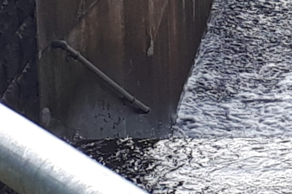
Figure 31: fixed handrail for access along a stepped spillway (Source: V. Pavlov)
You can also install a fixed ladder with a fall arrest system (to halt the fall of a falling worker) (figure 32).
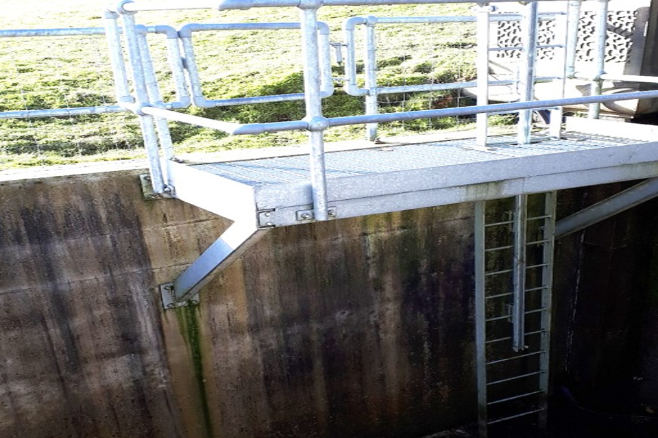
Figure 32: fixed ladder with fall arrest system for access to a spillway channel (Source: V. Pavlov)
Permanent access arrangements should not impact the hydraulic performance of the spillway or create any health and safety hazards for operators or the public.
If permanent direct access does not exist and it is not practical to provide them, you should provide suitable temporary access such as rope access or scaffold platforms.
You could also provide alternatives to direct access if the supervising engineer agrees they are suitable. These could include but are not limited to:
- binoculars or a camera mounted on a long reach pole (requiring suitable safe vantage points)
- a camera carried by a specially trained person (requiring suitable safe anchor points)
- a camera mounted on a remotely operated vehicle (drone)
You should carry out safety preparations for your own inspections and inspections carried out by supervising and inspecting engineers. These could include but are not limited to:
- preparing risk assessments and method statements and communicating them to people involved in the inspection
- cleaning the areas that will be inspected
- checking the permanent fixed access arrangements are safe
- checking whether those involved in the inspection are suitably trained
- providing any specialised safety or other equipment that may be needed (including attendance of trained persons to supervise)
For guidance on how to arrange safe access to the spillway to enable its close inspection, see the spillway examination guide.