MGN 645 (M) Load line length – policy clarification: hull form cut-outs, extensions and steps
Updated 25 July 2022

© Crown copyright 2022
This publication is licensed under the terms of the Open Government Licence v3.0 except where otherwise stated. To view this licence, visit nationalarchives.gov.uk/doc/open-government-licence/version/3 or write to the Information Policy Team, The National Archives, Kew, London TW9 4DU, or email: psi@nationalarchives.gov.uk.
Where we have identified any third party copyright information you will need to obtain permission from the copyright holders concerned.
This publication is available at https://www.gov.uk/government/publications/mgn-645-m-load-line-length-policy-clarification-hull-form-cut-outs-extensions-and-steps/mgn-645-m-load-line-length-policy-clarification-hull-form-cut-outs-extensions-and-steps
The diagrams featured in this document have not been correctly uploaded, please refer to the PDF document.
Summary
This Note clarifies UK interpretations for determining Load Line Length on vessel hull forms which feature cut-outs, removable end sections and stepped or recessed decks.
It highlights several methods by which Load Line Length (L) has been manipulated in order to obtain a value of less than 24 metres to avoid the vessel having to comply with the International Load Line Regulations or with the Large Yacht Codes as an equivalence. The way in which the MCA treats these various methods is shown, based, as far as possible, on straightforward interpretations of the Load Line regulations.
In addition, problems of interpretation can arise where features such as reverse sheer of the freeboard deck, sometimes found on yachts, are not catered for in the regulations. The MCA’s approaches to issues such as this are included herein with a view to a common approach being adopted.
The MCA, Certifying Authorities and Recognised Organisations authorised by the MCA consider the methods shown in Section 4 of attempting to reduce L to less than 24 metres to be unacceptable and will refuse to certify as SCVs any vessels using any of these methods to reduce L to below 24 metres.
1. Introduction
1.1 This MGN relates to vessels under 24 metres in Load Line Length (as defined in Regulation 3 of the International Convention on Load Lines 1966 and Protocol of 1988) the keels of which were laid on or after the date these regulations were implemented, and which were measured in accordance with the regulations in force at that time.
1.2 It should be noted that the Merchant Shipping (International Load Line Convention) (Amendment) Regulations 2018 (SI 2018 No. 155) are not referred to in the list of reference documents above as they apply only to internationally trading vessels having a Load Line Length of 24 metres and above whereas the Merchant Shipping (Load Line) Regulations 1998 and the 2000 Amendment Regulations continue to apply to vessels of under 24 metres in Load Line Length which may be trading internationally or domestically.
1.3 It should also be noted that, although there are similarities between Load Line Length and Tonnage Length as defined in the Merchant Shipping (Tonnage) Regulations 1997 (SI 1997 No. 1510) as amended, they are not identical; this Note includes references obtained only from the Load Line regulations and their official interpretations or the Recreational Craft Directive (RCD) ISO Standard 8666:2018.
2. Background
2.1 Load Line Length (L) is used to determine whether a vessel should comply with the UK national Load Line requirements for “small” vessels (i.e., those less than 24 metres in length) in SI 1998 No. 2241 (as amended by SI 2000 No. 1335), or an alternative equivalent such as a Code of Practice, or whether it should comply with SI 2018 No. 155, for internationally trading vessels of 24 metres length and over.
2.2 Identifying this 24-metre length breakpoint is particularly important when the determination of the length of the vessel on the 85% waterline or identification of the point of least moulded depth is not straightforward due to the design arrangements.
2.3 An example of how the breakpoint applies in the UK is that the MCA Small Commercial Vessel Codes of Practice apply to seagoing commercial vessels with L less than 24m as an alternative to compliance with the 1998/2000 UK Load Line Regulations. This is a proportionate approach as the latter regulations may become overly onerous when applied to “small” vessels.
2.4 The measurement and calculation of L is therefore an important element in determining which statutory requirements a vessel must comply with. The objective of this MGN is to explain how the MCA will interpret L in respect of design/measurement practices and the circumstances in which certain measurements will be applied.
3. Definitions
3.1 The following definitions are from the 1966 Load Line Convention and 1988 Protocol as amended. They have been extracted from MSIS41 Instructions for the guidance of Surveyors on International Load Line and include interpretations from various sources as used by the MCA.
3.2 Length (L)
(a) The length (L) shall be taken as 96% of the total length on a waterline at 85% of the least moulded depth measured from the top of the keel, or as the length from the fore side of the stem to the axis of the rudder stock on that waterline if that be greater.
(b) For ships without a rudder stock, the length (L) is to be taken as 96% of the waterline at 85% of the least moulded depth.
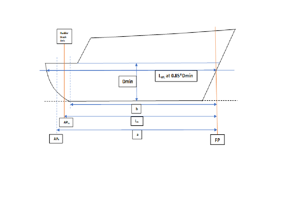
Figure 1: Derivation of L
Notes:
Dimension “a” represents a possible position of the AP (APa) if 96% of the length on the load waterline at 85% of the least moulded depth, Dmin, is greater than the length from the fore side of the stem to the axis of the rudder stock (Lrs).
Dimension “b” represents a possible position of the AP if 96% of the length on the load waterline at 85% of the least moulded depth, Dmin, is less than the length from the fore side of the stem to the axis of the rudder stock (Lrs). In this case, however, since “b” is less than Lrs it cannot govern the location of the AP which, by definition, will be at APrs.
If there is no rudder stock the AP is at APa.
FP (Forward Perpendicular) coincides with the fore side of the stem on the waterline on which the length (L) is measured. AP (After Perpendicular) coincides with the after end of the waterline on which the length (L) is measured (see figure 1).
MID is equidistant from the FP and AP; L/2 forward of the AP and L/2 aft of the FP.
D is the moulded depth in metres as defined in paragraph 3.3. Dmin is the least moulded depth in metres. It may not necessarily be at MID if the vessel has a rake of keel or sheer on the freeboard deck, (see figures 3 and 4, for example)
Lwl is the length in metres on the waterline at 0.85*Dmin.
(c) Where the stem contour is concave above the waterline at 85% of the least moulded depth, both the forward terminal of the total length and the foreside of the stem respectively shall be taken at the vertical projection to that waterline of the aftermost point of the stem contour (above that waterline) (see Figure 2).
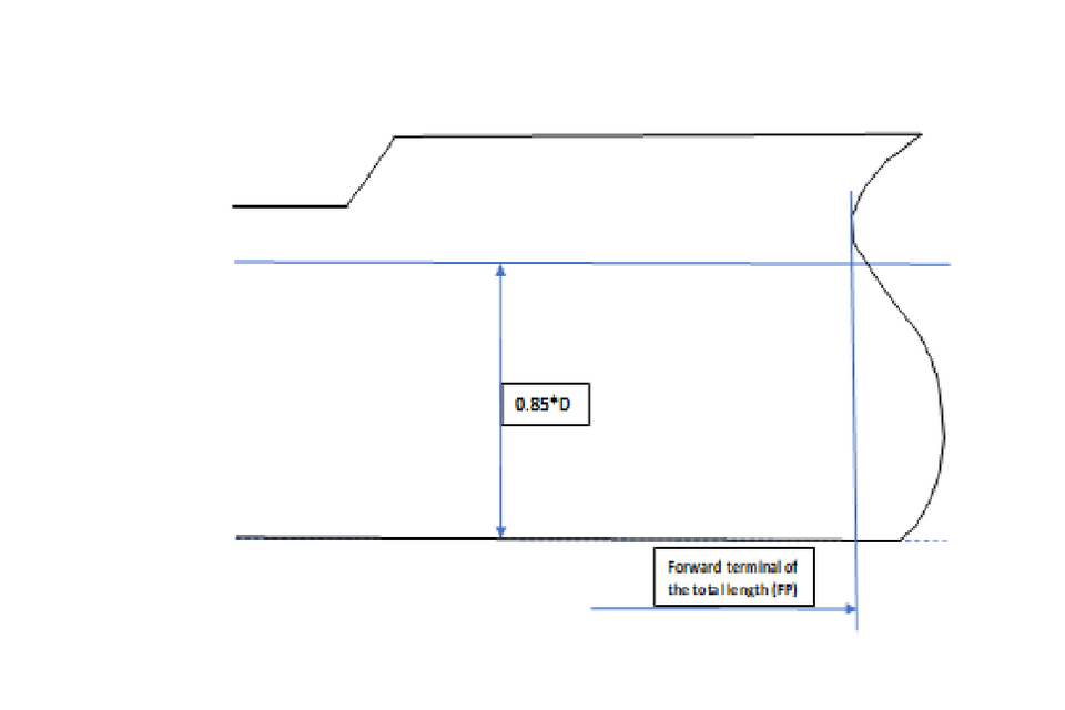
Figure 2: Example of length where the stem contour is concave
(d) In ships designed with a rake of keel the waterline on which this length is measured shall be parallel to the designed waterline at 85% of the least moulded depth Dmin, found by drawing a line parallel to the keel line of the vessel (including skeg) tangent to the moulded sheer line of the freeboard deck. The least moulded depth is the vertical distance measured from the top of the keel to the top of the freeboard deck beam at side at the point of tangency (see Figure 3).
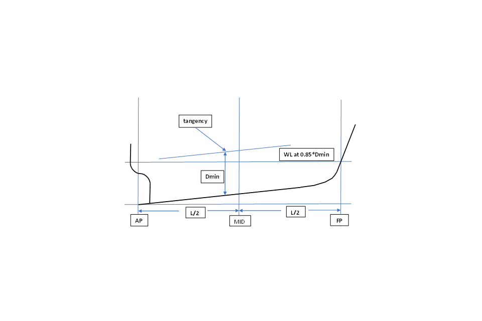
Figure 3: Waterline at 85% of the least moulded depth
Rake of keel – standard parabolic sheer
(e) Figure 3 above is taken directly from the Load Line Convention and shows a vessel with rake of keel and a standard parabolic sheer. Difficulties in determining Dmin may arise on vessels with “reverse” sheer. Figure 4 below illustrates one way in which Dmin could be determined in this case.
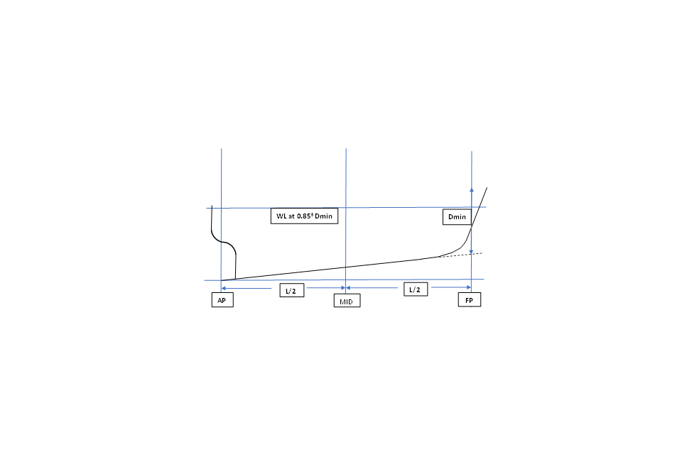
Figure 4: Waterline at 85% of the least moulded depth – reverse sheer
f) More complex arrangements would need to be considered on a case by case basis.
3.3 Moulded depth
(a) The moulded depth is the vertical distance measured from the top of the keel to the top of the freeboard deck beam at side. In wood and composite ships, the distance is measured from the lower edge of the keel rabbet. Where the form at the lower part of the midship section is of a hollow character, or where thick garboards are fitted, the distance is measured from the point where the line of the flat of the bottom continued inwards cuts the side of the keel.
(b) In ships having rounded gunwales, the moulded depth shall be measured to the point of intersection of the moulded lines of deck and sides, the lines extending as though the gunwale were of angular design.
(c) Where the freeboard deck is stepped and the raised part of the deck extends over the point at which the moulded depth is to be determined, the moulded depth shall be measured to a line of reference extending from the lower part of the deck along a line parallel with the raised part.
(d) Where the freeboard deck is discontinuous or stepped:
- (i) Where a step exists in the freeboard deck, creating a discontinuity extending over the full breadth of the ship, and this step is more than 1 metre in length (see figure 5), International Load Line Convention Regulation 3(9) should apply; Regulation 3(9) is shown in full in paragraph 3.4. A step 1 metre or less in length should be treated as a recess in accordance with paragraph (ii) below.
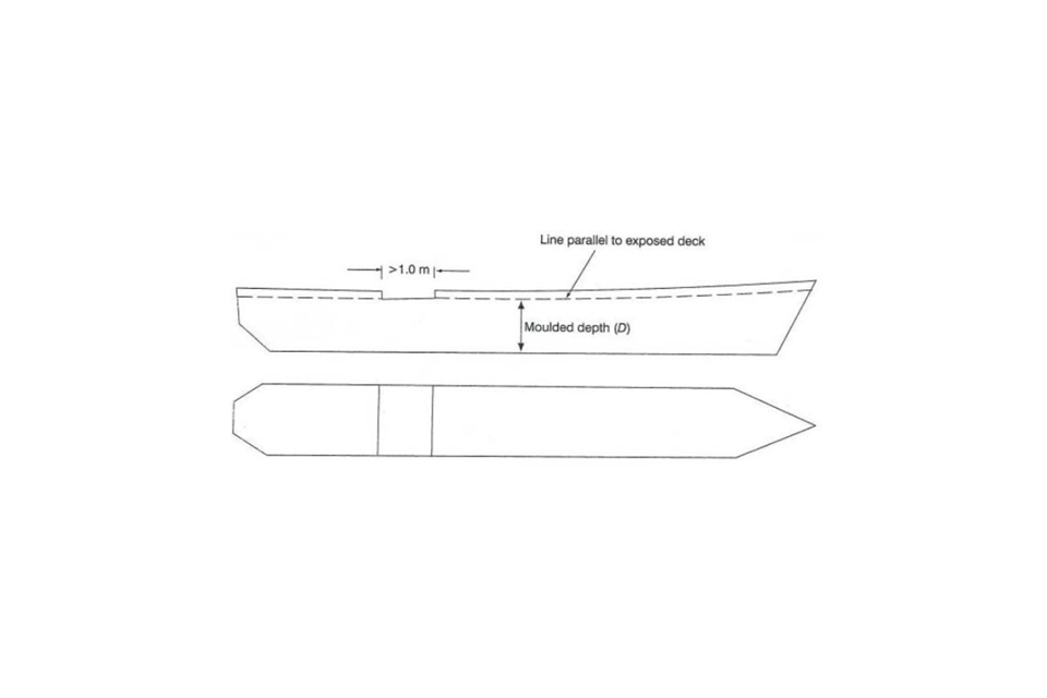
Figure 5: Step > 1 metre in length over full breadth of vessel
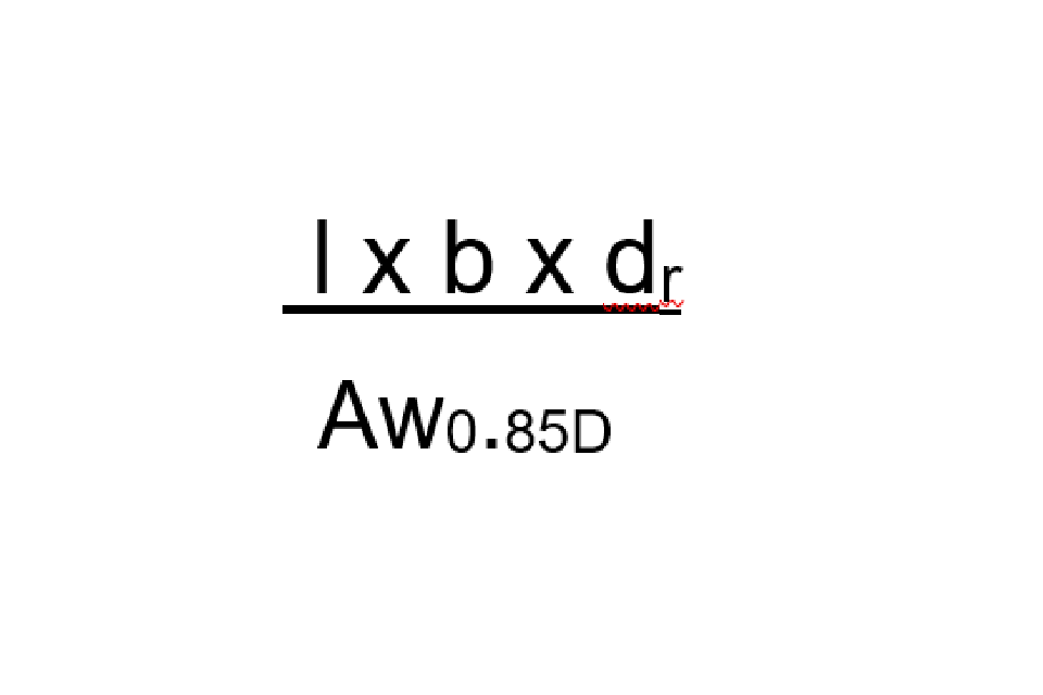
- (ii) Where a recess is arranged in the freeboard deck, and this recess does not extend to the side of the ship (see figure 6 below), the freeboard calculated without regard to the recess is to be corrected for the consequent loss of buoyancy. The correction should be equal to the value obtained by dividing the volume of the recess by the waterplane area of the ship (Aw) at 85% of the least moulded depth:
a. The correction should be a straight addition to the freeboard obtained after all other corrections have been applied, except bow height correction.
b. Where the freeboard, corrected for lost buoyancy as above, is greater than the minimum geometric freeboard determined on the basis of a moulded depth measured to the bottom of the recess, the latter value may be used.
c. Recesses in a second deck, designated as the freeboard deck, may be disregarded in this interpretation provided all openings in the weather deck are fitted with weathertight closing appliances.
d. Due regard is to be given to the drainage of exposed recesses and to free surface effects on stability.
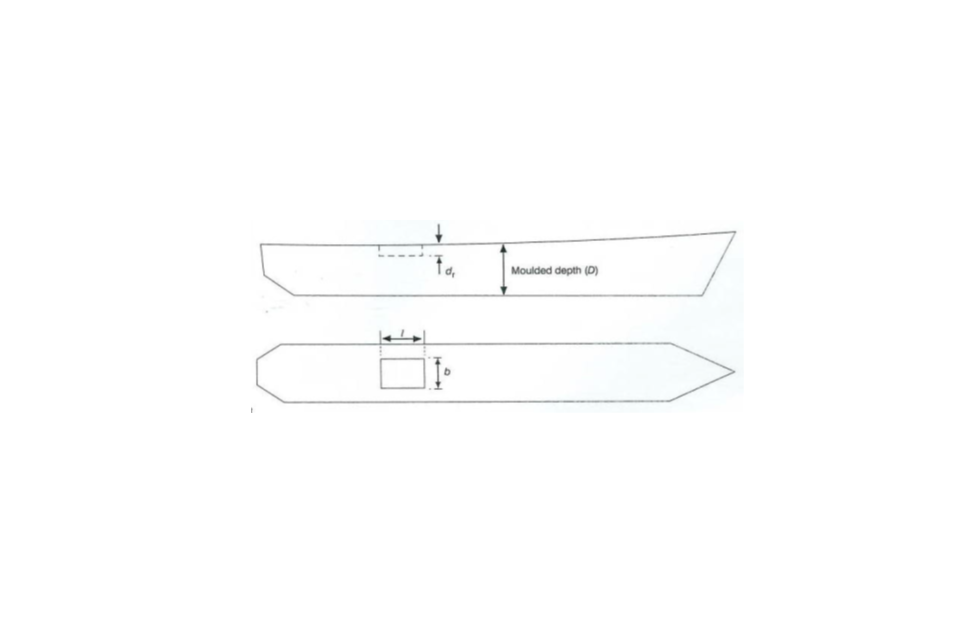
Figure 6: Recess in freeboard deck not extending to the side of the vessel
Correction is addition to freeboard equal to:
3.4 Freeboard deck
(a) The freeboard deck is normally the uppermost complete deck exposed to weather and sea, which has permanent means of closing all openings in the weather part thereof, and below which all openings in the sides of the ship are fitted with permanent means of watertight closing.
(b) Lower deck as a freeboard deck. At the option of the owner and subject to the approval of the Administration, a lower deck may be designated as the freeboard deck provided it is a complete and permanent deck continuous in a fore and aft direction at least between the machinery space and peak bulkheads and continuous athwartships.
-
(i) When this lower deck is stepped the lowest line of the deck and the continuation of that line parallel to the upper part of the deck is taken as the freeboard deck.
-
(ii) When a lower deck is designated as the freeboard deck, that part of the hull which extends above the freeboard deck is treated as a superstructure so far as concerns the application of the conditions of assignment and the calculation of freeboard. It is from this deck that the freeboard is calculated.
-
(iii) When a lower deck is designated as the freeboard deck, such deck as a minimum shall consist of suitably framed stringers at the ship sides and transversely at each watertight bulkhead which extends to the upper deck, within cargo spaces. The width of these stringers shall not be less than can be conveniently fitted having regard to the structure and the operation of the ship. Any arrangement of stringers shall be such that structural requirement can also be met.
(c) When the freeboard deck is discontinuous or stepped:
-
(i) Where a recess in the freeboard deck extends to the sides of the ship and is in excess of one metre in length, the lowest line of the exposed deck and the continuation of that line parallel to the upper part of the deck is taken as the freeboard deck (see figure 5, above).
-
(ii) Where a recess in the freeboard deck does not extend to the sides of the ship, the upper part of the deck is taken as the freeboard deck.
-
(iii) Recesses not extending from side to side in a deck below the exposed deck, designated as the freeboard deck, may be disregarded, provided all openings in the weather deck are fitted with weathertight closing appliances.
-
(iv) Due regard shall be given to the drainage of exposed recesses and to free surface effects on stability.
4. Methods employed to keep L below 24 metres
4.1 Cut-Outs
The MCA has become aware of vessels with cut-outs in way of the waterline at 0.85*D such that 96% of the length on that waterline is less than 24m. Such cut-out arrangements can lead to undesirable hydrodynamic characteristics or aesthetic considerations, so the cut-out is typically covered with a fairing piece which follows the more usual contours of a stem or stern. This fairing piece is generally bolted or otherwise fixed in place for the duration of the vessel’s life but, with the fairing piece in place and included in L calculations, the L of the vessel would be 24m or above. This is illustrated in figure 7 below.
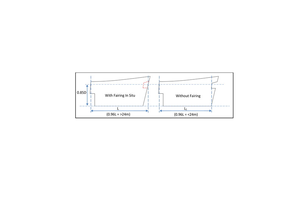
Figure 7: Cut-outs
4.2 Removeable End Sections
Examples have been seen where one or both end sections of a vessel are bolted-on (or otherwise fixed) at a vertical flat-plane bulkhead to artificially increase its length with an allegedly “removable” portion of hull which has been discounted from L calculations. This is similar to the example at 4.1 above but without the cut-out, and for similar reasons as described above for a fairing, the “removable” stem or stern portion(s) will clearly be in place during the normal operation of the vessel and may well be fixed in place for the duration of the vessel’s life.
4.3 Stepped Decks
As can be seen by the definition in 3.2 above, determination of L requires the least moulded depth to be ascertained. If the least moulded depth, and hence the 85% waterline, falls on an extended stepped deck then the vessel could be longer than if the stepped deck were excluded from the length determination. Section 5.3 of this MGN clarifies the circumstances under which stepped decks should be accounted for in the determination of L.
5. MCA Policies on the Methods Employed to keep L below 24 metres
5.1 Reduction of Length through Cut-Outs
Any addition or arrangement on the bow or stern of the vessel, the effect of which is to change the calculation of the Load Line Length (L) and which is normally in position during navigation will be taken into account in the calculation of L.
Cut-outs in the stem or stern, an example of which is shown in Figure 7 above, which serve no functional purpose and exist solely to circumvent the requirement for vessels with L of 24 metres and above to comply with the 1966 International Load Line Convention (as amended) will be treated as if they do not exist for the determination of L. Cut-outs will only be considered as contributing to a genuine reduction in L if they serve a purpose, such as, for example, an anchor housing.
As a result, for vessels where the cut-out portion of the 85% waterline has been covered by a fairing piece, the MCA, Certifying Authorities and Recognised Organisations authorised by the MCA will consider L to be the length with the fairing piece in place and will refuse to certify as SCVs any vessels using cut-outs to reduce L to below 24 metres
5.2 Extension of Length through Removable End Sections
Any portion of the hull in way of the waterline at 85% of the least moulded depth which is capable of being detached but which is fixed in place during the normal operation of the vessel is to be included in the calculation of L.
As the Load Line Convention makes no provision for the exclusion of detachable hull sections, the MCA relies instead on definitions taken from the Recreational Craft Directive (RCD) (see extract in section 7, below) for interpreting which structural components must be included, and which excluded when calculating L.
The value of L so calculated shall be used to determine whether the vessel’s length lies below the 24-metre break point mentioned above in section 2 and this interpretation will apply to vessels whose keels are laid on or after the date of publication of this MGN.
5.3 Extension of Length through Stepped Decks
Stepped decks aft have on occasions been excluded from the Load Line Length L. This practice encourages disproportionately long lengths whilst allowing the vessel to nominally remain below the 24-metre breakpoint.
Figures 8 and 9 below show steps or recesses in the freeboard deck which are assumed to extend to the full width of the vessel and illustrate how the measurement of Dmin and hence L depends on the length of the step or recess.
- (a) Step Length > 1 metre: Here the length of the full width step (x) is greater than 1 metre meaning that, according to section 3.3 (c) (i), above, the lowest line of the exposed deck aft and the continuation of that line parallel to the upper part of the deck is to be taken as the freeboard deck. Dmin is the least moulded depth from the top of keel to the freeboard deck, enabling the length on the waterline at 0.85D (LWL) to be measured. Length L is then either 0.96LWL at 0.85Dmin from the fore side of the stem (FP) or the distance from the FP to the axis of the rudder stock, whichever is greater. If there is no rudder stock, the AP is taken to be 0.96LWL at 0.85*Dmin metres aft of the FP
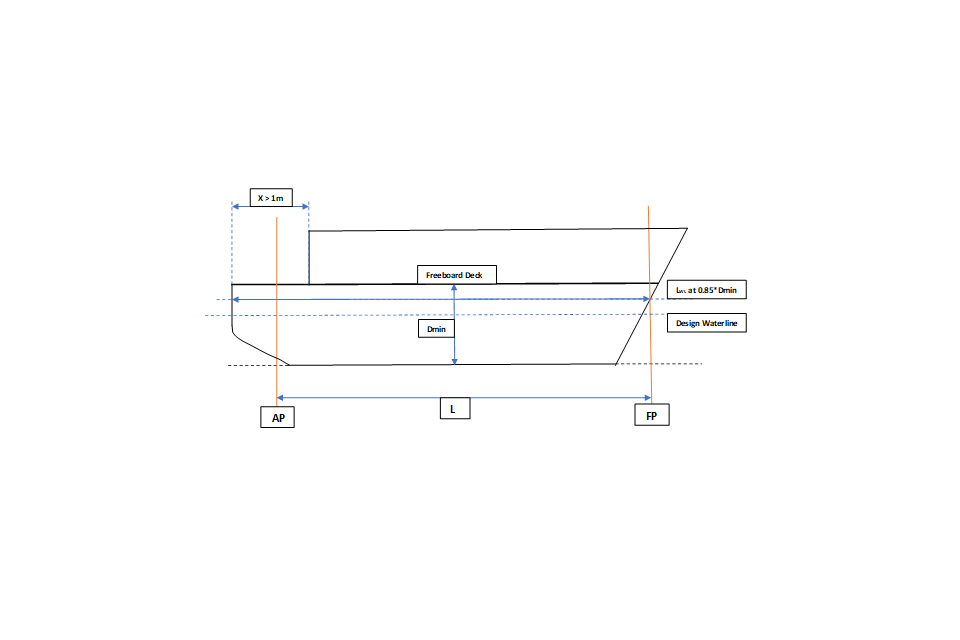
Figure 8: Step length > 1 metre
- (b) - Step Length ≤ 1 metre:
Taken from Section 3.2 (c), above, and based on IACS interpretation LL.48/Rev.2: -
A step 1 metre or less in length should be treated as a recess.
Paragraph 3 of this interpretation states “Recesses in a second deck, designated as the freeboard deck, may be disregarded in this interpretation provided all openings in the weather deck are fitted with weathertight closing appliances.
Therefore, the length of the full width step (x), now designated as a recess using this interpretation, being less than or equal to 1 metre may be disregarded, implying that the freeboard deck is assumed to continue to the aft end with the least moulded depth from the top of keel to the freeboard deck, Dmin, and LWL at 0.85*Dmin as shown in figure 9 below
Length L is then either 0.96LWL at 0.85Dmin from the fore side of the stem (FP) or the distance from the FP to the axis of the rudder stock, whichever is greater. If there is no rudder stock the AP is taken to be 0.96LWL at 0.85Dmin metres aft of the FP.”
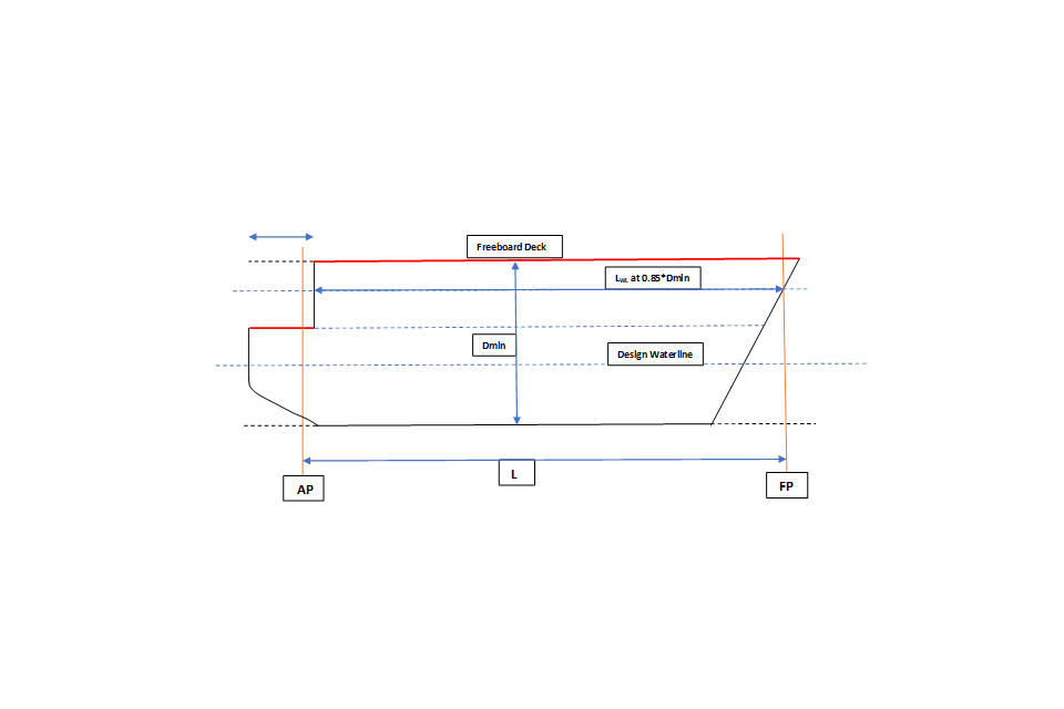
Figure 9: Step length ≤ 1 metre
6. Note on interpretation of “full width” step or recess
6.1 Some designs have been seen in which the lower level of the freeboard deck aft is protected by substantial bulwarks faired into the “sweep” from the upper to the lower level of the freeboard deck. Holes cut into these bulwarks to accommodate fairleads, drainage or ventilation openings, for example, are then said to constitute an opening which would enable the step or recess to be considered as “full width”. The MCA will only consider such holes in the bulwarks as rendering the step or recess “full width” if they are fairlead openings, or similar, which are essential for the safe operation of the vessel.
7. Length Measurement – RCD and Load Line
7.1 Hull Length (LH)
Hull Length. LH defined for the Recreational Craft Directive is as follows:
-
(a) Measured parallel to waterline.
-
(b) This length includes all structural and integral parts of the craft, such as stems or sterns, bulwarks, and hull/deck joints.
-
(c) This length excludes removable parts that can be detached in a non-destructive manner and without affecting the structural integrity of the craft, e.g. spars, bowsprits, pulpits at either end of the craft, stem-head fittings, rudders, outdrives, outboard motors and their mounting brackets and plates, diving platforms, boarding platforms, rubbing strakes, and fenders if they do not act as hydrostatic support when the watercraft is at rest or underway.
7.2 This definition may allow for a detachable stern section provided this section is open to sea and provides no hydrostatic buoyancy.
7.3 RCD Hull Length is defined differently to Load Line Length. There is no allowance in the Load Line Convention for detachable hull sections to be excluded. If the detachable hull section increases the total length at the waterline as determined in accordance with Load Line, then it will be included in the Load Line Length.
7.4 It is acknowledged that this may result in yachts that can be considered for RCD compliance that are over 24m Load Line Length. If it is intended to operate such a vessel commercially at any stage in its lifetime, then it would be considered over 24m for Load Line and so the Large Yacht Code/UK Load Line Regulations would apply.
7.5 If the detachable section of hull meets the RCD definition to allow exclusion from Hull Length, then it is easily detachable and does not contribute to the buoyancy of the vessel and so can be removed when the vessel is to be considered for commercial operation. The vessel should be able to operate safely within the agreed design envelope (sea state, vessel speed etc.) without the detachable section.
7.6 Commonly Asked Questions
| Question | Answer |
|---|---|
| Q1: If the removable part has functional components (e.g. bow roller, mooring/towing points) can it be excluded from hull length? | A1: Yes. Even if some functional fittings (such as cleats, windlass, fairlead …) are fixed to a removable part, it remains a “removable part”. Note: the definition in ISO 8666 refers to excluded examples of functional fittings such as rudders. |
| Q2: If a component has hydrodynamic performance but offers no hydrostatic support, can it be excluded from the hull length? | A2(i): Components that have no internal volume (e.g. a trim tab) give no hydrostatic support and are excluded from hull length. A2(ii): Detachable components that have an internal volume will move the centre of buoyancy of the craft. If the detachable component can affect the centre of buoyancy of the craft, it is considered to be providing hydrostatic support and thus must be included in hull length. A2(iii): If, however, the detachable component is open to the sea, there is no internal volume providing buoyancy and thus there is no hydrostatic support, so the component may be excluded from hull length. Note: internal volume means space for air or other low-density material. |
8. Policy Position
The MCA, Certifying Authorities and Recognised Organisations authorised are expected to use the clarifications, interpretations and principles expressed within this Marine Guidance Note when certifying vessels within the scope of this Note.
The MCA, Certifying Authorities and Recognised Organisations authorised by the MCA consider the methods shown in Section 4 of attempting to reduce L to less than 24 metres to be unacceptable and will refuse to certify as SCVs any vessels using any of these methods to reduce L to below 24 metres.
More information
UK Technical Services – Ship Standards
Maritime and Coastguard Agency
Spring Place
105 Commercial Road
Southampton
SO15 1EG
Telephone: +44 (0)203 817 2000
Email: loadline@mcga.gov.uk
Website: www.gov.uk/mca
General enquiries: infoline@mcga.gov.uk
Please note that all addresses and telephone numbers are correct at time of publishing.
Published: July 2022
© Crown Copyright 2021