Signal passed at danger near Ketton, Rutland, 24 March 2016
Published 14 June 2016

© Crown copyright 2016
This publication is licensed under the terms of the Open Government Licence v3.0 except where otherwise stated. To view this licence, visit nationalarchives.gov.uk/doc/open-government-licence/version/3 or write to the Information Policy Team, The National Archives, Kew, London TW9 4DU, or email: psi@nationalarchives.gov.uk.
Where we have identified any third party copyright information you will need to obtain permission from the copyright holders concerned.
This publication is available at https://www.gov.uk/government/publications/ketton-safety-digest/signal-passed-at-danger-near-ketton-rutland-24-march-2016
1. Important safety messages
To ensure the safe movement of trains, it is essential that drivers carry out a full brake test when coupling a locomotive to a train so that the operation of the brakes can be confirmed. It is important to test that the brakes on each part of the train are operational when the train uses more than one braking system.
It is also essential to carry out an effective running brake test as soon as practicable after departure, so that the train’s braking performance can be verified. This is vital where there is the potential for part of the train’s braking to be disabled, as the running brake test gives the driver a final opportunity to identify this condition.
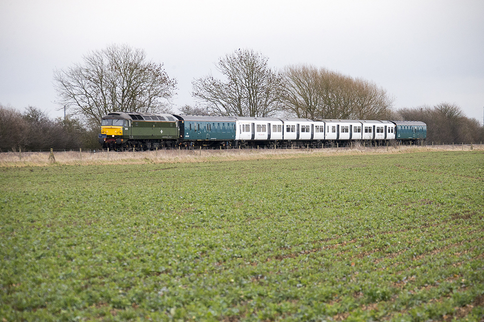
The train involved in the incident, shown travelling though countryside on an earlier journey. From left to right, the locomotive, the leading translator vehicle, the EMU and the rear translator vehicle. Image courtesy of Dave Lazenby.
2. Summary of the incident
A train operated by Rail Operations Group (ROG), consisting of a class 47 diesel-electric locomotive hauling a 4-car class 321 electric multiple unit (EMU), passed signal K3 (between Ketton and Stamford), which was showing a stop aspect, by about 10 metres. No-one was injured and there was no damage to either the train or the infrastructure.
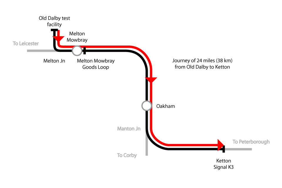
Simplified map showing route the train took from the Old Dalby test facility through Melton Mowbray and Oakham before approaching signal K3 at Ketton (not to scale)
3. Cause of the incident
The EMU was being hauled, unpowered, back to Ilford depot, in East London, following refurbishment work at the Old Dalby test facility, near Melton Mowbray. The train was formed with a translator vehicle coupled to each end of the EMU and the locomotive at the front.
The translator vehicles provided a mechanical means of connecting the screw coupling on the locomotive to the ‘tightlock’ couplings fitted on the EMU. They also provide an interface between the air-pressure controlled braking system on the locomotive and the electrically controlled braking system on the EMU.
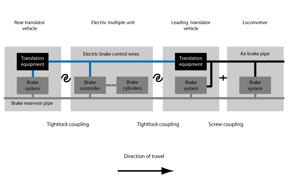
Diagram showing the components of the train coupling systems and braking systems, correctly configured for train movements
In normal operation, the driver controls the pressure in the air brake pipe in the locomotive, which indirectly operates the brakes on the locomotive and on the lead translator vehicle. The lead translator vehicle converts the pressure in the air brake pipe to electrical signals which are sent to the EMU and on to the rear translator vehicle. These signals then control the brake systems on the EMU and on the rear translator vehicle.
Prior to the locomotive and translator vehicles arriving at Old Dalby test facility, the EMU had been inspected by a vehicle examiner working on behalf of ROG. The vehicle examiner issued a certificate indicating that the vehicle was fit to operate on the main line, but also showing that a brake test had not been carried out and stating that a functional test of the brakes was required before departure. This certificate was left at the Old Dalby test facility office and was collected by the ROG train crew after the locomotive had coupled to the train.
The ROG driver, in conjunction with a ROG shunter, had coupled the locomotive and translator vehicles to the EMU and set up the translator vehicles. Section 4.2 of railway rule book (GE/RT8000) Module TW1 then required a brake continuity test to be carried out. The ROG procedure for this test required the shunter to operate the emergency brake handle in the rear translator vehicle and confirm that the brake cylinder pressure increased, thus applying the brakes.
The ROG procedure also required the driver to operate the brakes in steps, with the shunter observing that the same brake steps were applied at the rear translator vehicle. Both these tests were completed before departure, and demonstrated that the brakes were operational at the front and the rear of the train. This is typical of the brake continuity test normally carried out on locomotive-hauled trains.
The ROG procedure also required the shunter to observe that the brake cylinder pressures in the leading cab of the EMU responded to different brake steps applied by the driver in the locomotive. This additional test was intended to confirm that the electrically controlled brakes in the EMU were also operating. This test was not done.
At this time the brake cylinders in the EMU were isolated, and so would not have responded to the electrical brake control signals generated by the lead translator vehicle. It is not clear when the EMU brake cylinders had been isolated (by closing isolating valves), or by whom, but this is likely to have been done prior to the ROG staff preparing the train. However, despite the isolation, the electrical brake control signals were still able to pass through the EMU to operate the brakes on the rear translator vehicle, resulting in the successful brake continuity test. Omission of the test in the EMU cab meant that the driver and shunter did not identify that only the locomotive and both translator vehicles had effective brakes, while the four vehicles of the EMU were unbraked.
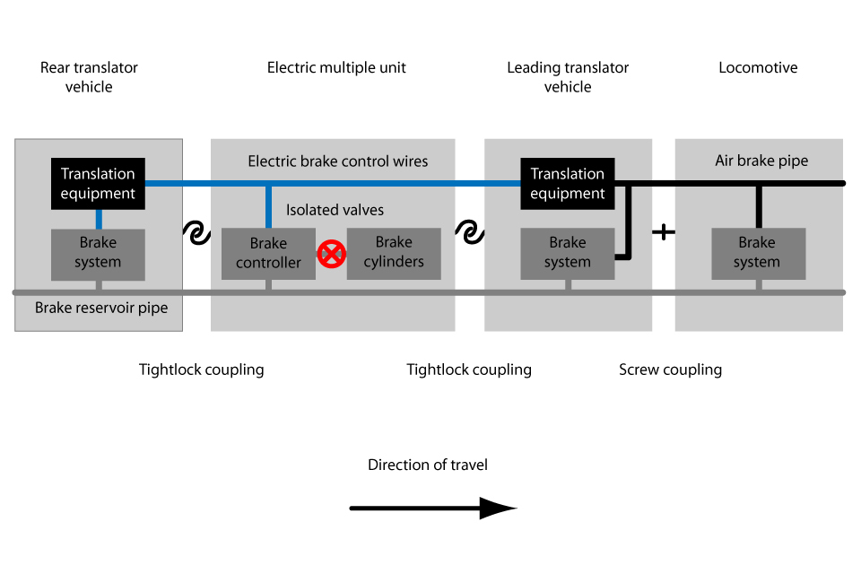
Diagram showing the components of the train coupling systems and braking systems with the EMU brakes isolated
Section 4.6 of railway rule book (GE/RT8000) Module TW1 required the driver to carry out a running brake test ‘at the first opportunity after beginning the journey’. This requires a driver to test the train brakes ‘from a speed that is high enough to be sure that the brake is operating effectively and the speed of the train is being reduced’. The driver carried out a running brake test between Old Dalby and Melton Junction at low speed (approximately 20 mph, or 32 km/h) and with an initial (low) brake application. The driver felt the train decelerate at a rate that did not alert him to the EMU brakes being inoperative. Further brake applications were made at low speed between Melton Junction and Melton Mowbray Goods Loop to control the train speed, but the observed decelerations did not alert the driver to the inoperative EMU brakes.
After departing from Melton Mowbray, the driver accelerated the train to 64 mph (103 km/h) and carried out another low application running brake test from a higher speed than during the earlier running brake test. Again, this did not alert the driver to the reduced braking available, possibly because the train was running uphill at the time. Three further brake applications, while controlling the train’s speed, did not alert the driver to the train’s reduced braking capability, probably because two of them were on uphill stretches of line and the other was relatively brief.
While running at 69 mph (111 km/h) near Ketton signal box, on a downhill gradient of 1 in 165, the driver made an initial brake application on sighting a signal showing a yellow caution aspect. He quickly recognised that the train was not slowing as rapidly as expected and made a full service brake application seven seconds after first applying the brakes. He applied the emergency brake nineteen seconds later, although this did not provide additional retardation because full braking was already applied. The train continued to decelerate more slowly than expected, before coming to a stop about 10 metres past the next signal (K3) which was showing a red stop aspect.
After reporting the incident, the driver was authorised by the signaller to take the train at reduced speed to Peterborough.
4. Previous similar occurrences
The importance of compliance with train preparation procedures is discussed in RAIB reports 08/2006 (Hatherley) and 06/2007 (Basford Hall), although the circumstances in both cases were very different to this incident. The need for an adequate running brake test is discussed in RAIB reports 02/2011 (Carstairs) and 03/2011 (Carrbridge).
You can print this safety digest.