5. Axles, wheels, tyres and suspension
Axle, wheel bearing, wheel and tyres, tyre pressure monitoring system (TPMS), and suspension (including springs, shock absorbers, and suspension arms and joints) rules and inspection for car and passenger vehicle MOT tests.
In this section
5.1.1. Axles
It’s recommended that you use wheel play detectors when checking axle security on beam axles.
| Defect reference | Defect | Category |
|---|---|---|
| (a) | An axle fractured or deformed | Dangerous |
| (b)(i) | An axle insecure or with loose fixing bolts | Major |
| (b)(ii) | An axle insecure such that stability is impaired or functionality affected | Dangerous |
| (c)(i) | An axle with an unsafe modification | Major |
| (c)(ii) | An axle modified so that vehicle stability is impaired or axle functionality affected | Dangerous |
5.1.2. Stub axles
To check the condition of stub axles:
-
Jack up the front of the vehicle so that the front wheels are off the ground.
-
Observe the relative vertical movement between components.
-
Use a suitable bar under each wheel in turn and lever upwards, looking for play in components.
Then check for play in components using either:
- wheel play detectors in the side to side mode
- rocking each wheel by hand or with a bar in the wheel
| Defect reference | Defect | Category |
|---|---|---|
| (a) | A stub axle fractured | Dangerous |
| (b)(i) | A stub axle swivel pin and/or bush excessively worn | Major |
| (b)(ii) | A stub axle swivel pin and/or bush is so excessive the stub axle is likely to become insecure or directional stability is impaired | Dangerous |
| (c)(i) | Movement between the stub axle and axle beam is excessive | Major |
| (c)(ii) | Movement between the stub axle and axle beam insecure or directional stability is impaired | Dangerous |
| (d)(i) | A king pin loose in the axle beam | Major |
| (d)(ii) | A king pin so loose it is likely to affect directional stability | Dangerous |
5.1.3. Wheel bearings
Vehicles with a DGW more than 5,000kg do not need to have rear wheel bearings inspected.
Assess play in wheel bearings by either:
- rocking the wheels in turn while they’re jacked clear of the ground
- using wheel play detectors in the side to side mode
With each wheel raised clear of the ground, spin the wheel and listen for roughness in the bearings.
| Defect reference | Defect | Category |
|---|---|---|
| (a)(i) | A wheel bearing with excessive play | Major |
| (a)(ii) | A wheel bearing play so excessive it is likely to break up or directional control impaired | Dangerous |
| (b)(i) | A wheel bearing excessively rough | Major |
| (b)(ii) | A wheel bearing likely to collapse | Dangerous |
In this section
5.2.1. Road wheel and hub
| Defect reference | Defect | Category |
|---|---|---|
| (a)(i) | A wheel with a loose or missing wheel nut, bolt or stud | Major |
| (a)(ii) | A wheel with more than one loose or missing wheel nut, bolt or stud | Dangerous |
| (b)(i) | A spigot mounted wheel hub excessively worn or damaged | Major |
| (b)(ii) | A spigot mounted wheel hub worn or damaged to the extent that wheel security is adversely affected | Dangerous |
5.2.2. Road wheel condition
You only need to inspect the road wheels fitted to the vehicle at the time of the inspection. If you notice a defect on a spare wheel, you should tell the vehicle presenter about it.
You must not remove wheel hub caps.
You can accept abutting ends on detachable spring retaining rings on wheel rims of semi-drop centre type (identified by the ends of the ring shaped to interlock) as long as the retainer is adequately and safely located in the wheel rim.
| Defect reference | Defect | Category |
|---|---|---|
| (a) | Any fracture or welding defect on a wheel | Dangerous |
| (b)(i) | A tyre retaining ring not correctly fitted | Major |
| (b)(ii) | A tyre retaining ring likely to come off | Dangerous |
| (c)(i) | A wheel badly distorted or wear between wheel and hub at spigot mounting | Major |
| (c)(ii) | A wheel distorted or worn to the extent the wheel or tyre is likely to become detached | Dangerous |
| (d) | A wheel and its fixings not compatible | Major |
5.2.3. Tyres
You only need to inspect the tyres fitted to the road wheels at the time of the inspection. If you notice a defect on a spare tyre, you should advise the vehicle presenter.
Size
The aspect ratio of a tyre is included in the size marking. For example, a 215/55R15 has an aspect ratio of 55%.
‘Standard’ car tyres have a nominal aspect ratio of 82% (unless marked otherwise) and these are almost identical in size to tyres with an aspect ratio of 80%. They can be safely mixed in any configuration on a vehicle.
Some tyres may be marked with two sizes. For example, a 185/75R14 tyre may be dual marked 185R14. In such cases, you can accept either marking.
Load rating - Classes 5 and 7 only
A tyre load rating table is in Appendix B.
Make sure the tyre load rating is suitable for the axle weight.
You can find the permitted maximum laden weight of an axle on the manufacturer’s plate.
If axle weights are not displayed on the manufacturer’s plate, you must assume that the load capacity of the tyres are suitable, unless there’s indisputable evidence to suggest otherwise.
If a goods vehicle has a ‘Ministry’ plate showing lower axle weights not to be exceeded in Great Britain, you must use those instead of the ones on the manufacturer’s plate.
Speed rating - Classes 5 and 7 only
A tyre’s speed rating is shown on the sidewall as a letter and usually precedes or follows the load rating. Speed ratings from A to K are unacceptable, with the exception of H.
If no speed rating is shown it must be assumed that the minimum requirements are met.
Load ratings for low speed rated tyres - Class 5 vehicles only
Tyres must be suitable for use up to 70mph (L speed rating) unless the vehicle is a ‘restricted speed vehicle’.
If the tyre can carry the maximum permitted axle weight of the vehicle, these vehicles can use tyres with a lower speed rating tyres up to 70mph as follows:
- K speed rating – but the tyre’s carrying capacity is reduced by 3%
- J speed rating – but the tyre’s carrying capacity is reduced by 7%
For example, K speed rating tyres can be used at 70mph if the load is reduced as follows: 146/143K = 6,000kg single or 10,900kg dual - less 3% = 5,820kg single or 10,580kg dual
You must not accept a tyre load rating that’s less than the maximum permitted axle weight.
Structure
Tyres of different types of structure, such as radial-ply and cross-ply, must not be mixed on the same axle.
Steel and fabric radial-ply tyres are considered to be the same structure.
Run flat and conventional tyres can be mixed on the same axle, although this is not recommended.
Condition and fitment
Evidence of a tyre contacting a part of the vehicle, such as due to tyre flexing or suspension movement, is not considered to be a defect. A vehicle should only be rejected if the tyre is fouling a part of the vehicle at the time of test.
Some vehicles have lock stops comprising rubbing pads on the body that the front tyres may contact on a full lock. These are acceptable if they are properly maintained so that they do not damage the tyres.
When assessing cuts in a tyre, it is permissible to check whether a cut is deep enough to reach the ply or cord by using a blunt instrument to open the cut taking care not to cause further damage.
The following criteria should be used when assessing a cut in a tyre:
- any ply or cord that can be seen without touching the tyre - fail
- if by folding back rubber or opening a cut with a blunt instrument, so as not to cause further damage, exposed ply or cord can be seen irrespective of the size of the cut - fail
- if a cut which is more than 25mm or 10% of the section width whichever is the greater, is opened with a blunt instrument and cords can be felt but not seen - fail
Before failing a cut, you must make sure it’s the cords that you can feel not a foreign object. If you’re not sure, then you should pass and advise.
When assessing lumps or bulges in a radial ply tyre, care should be taken to distinguish between normal undulations in the carcass, resulting from manufacturing, and lumps or bulges caused by structural deterioration.
Take extra care with stretched tyres because they’re more prone to sidewall damage.
Recut tyres are only permitted on:
- vehicles over 3,050kg ULW
- goods vehicles with an ULW of at least 2,540kg having at least 16 inch (405mm) diameter wheels
- passenger vehicles with an ULW of at least 2,540kg having 8 or more passenger seats
You should only accept tyres with NHS, Not for Highway Use or similar markings if they have an ‘E’ marking and a number contained within a circle. Adjacent to this circle, the sidewall must also be marked with a six digit number, which may be preceded by 75R or similar marking (see example below).

Direction of rotation may be indicated by an arrow and/or words, but an arrow by itself should not be taken to indicate direction of rotation.
Asymmetric tyres are marked with correct fitment information on the sidewall, such as ‘outside’. However, if an asymmetric tyre is fitted the wrong way around it is not to be considered a reason for rejection. The presenter should be advised.
Tread depth
A tread pattern is the combination of plain surfaces and grooves extending across the breadth of the tread and round the entire circumference. It excludes any tie-bars, tread wear indicators, or features designed to wear out substantially before the remainder of the pattern, and other minor features.
In simple terms, grooves containing tread wear indicators (TWI) or grooves cut as deep as those containing the wear indicators when new, are considered to be primary grooves. Other grooves or sipes that are not cut as deep as the primary grooves are secondary grooves and are not to be considered when assessing tread depth.
The ‘breadth of tread’ is the part of the tyre which can contact the road under normal conditions of use measured at 90 degrees to the peripheral line of the tread.
Different vehicles require different tread depths.
The following vehicles first used on or after 3 January 1933 need 1.6mm tread depth:
- passenger vehicles with a maximum of 8 passenger seats, excluding the driver’s seat
- goods vehicles or dual-purpose vehicles not exceeding 3,500kg DGW
- tricycles with an ULW more than 410kg and all quadricycles
- goods vehicles which are zero emission vehicles with a maximum gross weight over 3,500kg but not exceeding 4,250kg
The primary grooves of the tread pattern must be at least 1.6mm deep within the central three-quarters of the breadth of tread and around the entire outer circumference of the tyre (see diagram 1).
Either side of the central three-quarters of the tyre can be devoid of tread (‘bald’).
Diagram 1. Primary and secondary grooves in tyre tread pattern

The following vehicles must have 1.0mm tread depth:
- vehicles first used before 3 January 1933
- passenger vehicles with more than 8 passenger seats excluding the driver’s seat
- tricycles with an ULW not exceeding 410kg with an engine capacity greater than 50cc
- tricycles with an ULW not exceeding 410kg which are electrically powered
The tread pattern must be visible over the whole tread area (see diagram 2), and have a depth of at least 1.0mm throughout a single band of at least three-quarters over any section of the breadth of tread round the entire outer circumference of the tyre.
The 1.0mm tread depth requirement applies to the whole tread width if the original tread pattern did not extend beyond three-quarters of the tyre width when new.
Tricycles with an ULW not exceeding 410kg with an engine capacity not greater than 50cc do not need to have 1mm of tread. However, they must have a visible tread pattern around the entire circumference and across the whole breadth of the tread.
Diagram 2. Tread pattern visibility

Tyre pressure monitoring system (TPMS)
The inspection of the tyre pressure monitoring system (TPMS) is for M1 vehicles first used on or after 1 January 2012.
The inspection of the tyre pressure monitoring system (TPMS) does not apply to motor caravans, ambulances and hearses approved as M1 with a gross vehicle weight (GVW) of more than 2,500kg.
The TPMS warning lamp (see diagram 3) will generally illuminate and go off again when the ignition is switched on. If the system has identified a previous pressure loss, the lamp will remain illuminated. This does not automatically mean the system has a malfunction. In the event of a system malfunction, the lamp may flash a number of times and then remain on.
Warning messages on dashboard displays are not a defect in their own right, but may assist the tester in determining that the warning lamp is illuminated because a malfunction exists.
If it is unclear the warning lamp is indicating a system malfunction and not a simply indicating that one or more tyre pressures are low, then advisory information should be added to the test result.
Diagram 3. Example of a TPMS warning lamp

Tyre age
The check of tyre age applies to all vehicles with more than 8 passenger seats, other than vehicles of historical interest.
Tyre age is determined by the date code on the sidewall and will be a three or four-digit code. Tyres with a three-digit code will be more than 10 years old.
The code is usually located in a ‘window’ on the sidewall and may or may not be located at the end of the DOT number (see image below).
The first two digits of the code represent the week of manufacture of the tyre and the second two digits represent the year of manufacture. In the example above, the tyre was manufactured in week 35 of 2016.
Tyres over ten years old at the time of test must be failed if they are on:
- any front steered axle
- any rear axle of a minibus with a single wheel fitment.
Tyres not displaying a date code must also be failed. However, date codes are only required to be marked on one side of the tyre so it may not be possible to see the date code on twin wheel fitments. Under these circumstances you should advise the presenter and assume the date code is present and the tyre age is acceptable.
On tyres where the date code is illegible, for example, due to kerbing or deliberate tampering, a major or minor defect must be recorded, depending on the location of the tyre.
Retreaded tyres
Remoulded/retreaded tyres may have two date codes. One being the original code and the other being the date of retreading. In this case the most recent date code must be used.
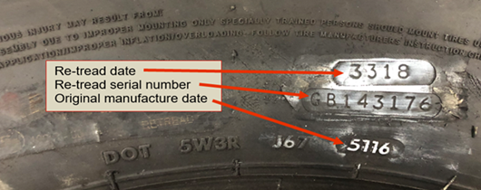
The appearance of the date code on retreaded tyres may be different from the original date code and may be branded rather than moulded.
| Defect reference | Defect | Category |
|---|---|---|
| (a)(i) | A tyre load capacity or speed rating not in accordance with the minimum requirements | Major |
| (a)(ii) | A tyre load capacity insufficient for axle presented weight | Dangerous |
| (b) | Tyres on the same axle or on twin wheels are different sizes | Major |
| (c) | Tyres on the same axle of different structure | Major |
| (d)(i) | A tyre with a cut in excess of the requirements deep enough to reach the ply or cords | Major |
| (d)(ii) | A tyre with a lump, bulge or tear caused by separation or partial failure of its structure, including any lifting of the tread rubber or with cords exposed or damaged | Dangerous |
| (e) | Tyre tread depth not in accordance with the requirements | Dangerous |
| (f) | A tyre fouling a part of the vehicle | Major |
| (g) | A recut tyre fitted to a vehicle not permitted to be fitted with recut tyres | Major |
| (h) | Tyre pressure monitoring system malfunctioning or obviously not working | Major |
| (i) | A tyre not fitted in compliance with the manufacturer’s sidewall instructions | Major |
| (j) | A tyre valve seriously damaged or misaligned likely to cause sudden deflation of the tyre | Dangerous |
| (k) | A tyre incorrectly seated on the wheel rim | Major |
| (l) | Tyre obviously under-inflated | Minor |
| (m) | A tyre over ten years old is fitted to a front steered axle of a bus, coach, or any axle on a minibus with a single wheel fitment | Dangerous |
| (n)(i) | A date code illegible on a tyre fitted to a rear axle of a bus or coach | Minor |
| (n)(ii) | A date code illegible or not visible on a tyre fitted to a front steered axle of a bus or coach or any axle on a minibus with a single wheel fitment | Major |
In this section
- 5.3.1. Springs
- 5.3.2. Shock absorbers
- 5.3.3. Suspension arms, rods, struts, sub-frames, anti-roll bars etc.
- 5.3.4. Suspension joints, pins and bushes
- 5.3.5. Gas, air and fluid suspension
- 5.3.6. Complete suspension system
5.3.1. Springs
This inspection includes bonded suspension units.
You should not reject vehicles with leaf spring type suspension if modified spring anchor or shackle brackets are fitted and there are more mounting holes in the bracket than holes in the chassis.
Defect 5.3.1.b also applies to that part of a leaf spring which is curled to prevent disengagement from a slipper.
You should assess the security of a coil spring to the chassis or axle when jacking and lowering the vehicle. If the spring does not correctly locate when the suspension is returned to its normal running position, then you should reject it for being insecurely attached.
You do not need to jack the rear wheels of vehicles with a DGW more than 5,000kg.
Unsafe modifications include:
- welded repairs
- the use of excessive heat to highly stressed components (see Appendix A)
- modifications likely to affect the roadworthiness of the vehicle
A missing bump stop rubber is not a reason for rejection.
| Defect reference | Defect | Category |
|---|---|---|
| (a)(i) | A spring insecurely attached to chassis or axle | Major |
| (a)(ii) | A spring with fixings loose to the extent that relative movement is visible | Dangerous |
| (b)(i) | A spring or spring component fractured or seriously weakened | Major |
| (b)(ii) | A spring main leaf fractured | Dangerous |
| (c)(i) | A spring missing | Major |
| (c)(ii) | A spring missing and directional control affected | Dangerous |
| (d)(i) | A spring with an unsafe modification | Major |
| (d)(ii) | A spring modified so that the suspension is inoperative | Dangerous |
5.3.2. Shock absorbers
You should reject a missing shock absorber only if they were fitted as standard.
A shock absorber must be rejected if negligible damping effect becomes evident at any point during the inspection.
Slight seepage causing a film of fluid on a shock absorber is not a reason for rejection.
| Defect reference | Defect | Category |
|---|---|---|
| (a)(i) | A shock absorber insecurely attached to chassis or axle | Major |
| (a)(ii) | A shock absorber missing or likely to become detached | Dangerous |
| (b) | A shock absorber damaged to the extent that it does not function or showing signs of severe leakage | Major |
| (c) | A shock absorber bush excessively worn | Major |
| (d) | A shock absorber which has negligible damping effect | Major |
5.3.3. Suspension arms, rods, struts, sub-frames, anti-roll bars etc.
Some vehicles use thin gauge steel pressings for some highly stressed suspension components. Many of these parts have hollow ‘box sections’ or up-facing areas that can collect road dirt, salt or other chemicals that can cause severe local corrosion.
You should pay special attention to these components.
You can find guidance on assessing corrosion in Appendix A.
It may be easier to inspect suspension components with the wheels jacked for the checks in Section 5.3.4. You do not need to jack the rear wheels of vehicles with a DGW more than 5,000kg.
Unsafe modifications include:
- welded repairs
- the use of excessive heat to highly stressed components (see Appendix A)
- modifications likely to affect the roadworthiness of the vehicle
A missing bump stop rubber is not a reason for failure.
| Defect reference | Defect | Category |
|---|---|---|
| (a)(i) | A suspension component insecurely attached to chassis or axle | Major |
| (a)(ii) | A suspension component missing, likely to become detached or directional stability impaired | Dangerous |
| (b)(i) | A suspension component excessively damaged or corroded | Major |
| (b)(ii) | A suspension component fractured or likely to fail | Dangerous |
| (c)(i) | A suspension component with an unsafe modification | Major |
| (c)(ii) | A suspension component modified so that the suspension is inoperative or likely to foul other components | Dangerous |
5.3.4. Suspension joints, pins and bushes
Some rubber/synthetic bushes are designed to provide a comparatively high degree of compliance and are therefore likely to show some movement.
You should only reject rubber or synthetic bushes when you can see serious deterioration of the bonding or flexible material.
Many MacPherson strut top bushes are designed to have significant lateral play when the suspension is hanging free. You should only reject MacPherson strut top bushes when play is due to wear or maladjustment.
You should assess wear or play in spring pins and bushes using either:
- a small pinch bar
- wheel play detectors
Wear is excessive if play is more than:
- 2mm for a 12mm diameter pin
- 3mm for a 25mm diameter pin
- 10% of the pin diameter for pins over 25mm diameter
To fully assess the condition of front suspension components you should use wheel play detectors.
If wheel play detectors are not available, do the following:
-
Jack the front wheels clear of the ground, place a suitable bar under each wheel in turn and lever upwards, looking for play in components.
-
Rock and shake the wheels to check for play.
-
Use an assistant to rock and shake the wheels while you examine the relevant items.
For vehicles with front suspension systems that do not have the torsion bar or spring force acting on the lower suspension arm follow these steps:
-
Make sure the front wheels are resting on unlocked turning plates.
-
Grasp the top of each wheel and push and pull vigorously in and out to check for play.
-
Grasp each wheel at the 3 o’clock and 9 o’clock positions and push and pull vigorously without pivoting the wheel to check for play.
-
Use an assistant to shake the wheels as per item 3, whilst observing the relevant components.
Method of jacking
Use your experience and judgement when jacking various suspension types. Vehicles may require jacking in more than one position separately to ensure any force is removed from ball joints to allow a proper examination for wear/play.
Vehicles with front suspension types that have the torsion bar or spring force acting on the lower suspension arm must be jacked under the lower suspension arm so that the suspension spring force is removed from the ball joints as shown.
Beam axles should be jacked under the beam.
All other suspension types must be jacked so the suspension hangs freely.
Diagram 4. Jacking up vehicles with front suspension

Rear axles
Ensure the jacking equipment is positioned to allow the safe examination of components without risk of injury or damage to the vehicle.
Use your experience and judgement when positioning the jacking equipment to ensure that suspension spring force is removed from components to allow a proper examination for wear/play.
On some vehicles it may be necessary to jack in more than one position to carry out a full examination.
You do not need to jack the rear wheels of vehicles with a DGW more than 5,000kg.
| Defect reference | Defect | Category |
|---|---|---|
| (a)(i) | A suspension pin, bush, joint or bearing excessively worn | Major |
| (a)(ii) | A suspension pin, bush, joint or bearing likely to become detached | Dangerous |
| (b)(i) | A suspension joint dust cover severely deteriorated | Minor |
| (b)(ii) | A suspension joint dust cover missing or no longer prevents the ingress of dirt etc. | Major |
5.3.5. Gas, air and fluid suspension
When testing vehicles with these suspension types, you should be aware of the health and safety hazards.
See the Introduction health and safety section for guidance.
| Defect reference | Defect | Category |
|---|---|---|
| (a) | A gas, air or fluid suspension system inoperative | Dangerous |
| (b)(i) | A gas, air or fluid suspension system component damaged, modified or deteriorated in a way that it would adversely affect the functioning of the system | Major |
| (b)(ii) | A gas, air or fluid suspension system component damaged, modified or deteriorated in a way that its function is seriously affected | Dangerous |
| (c) | An obvious leak from any part of the system | Major |
5.3.6. Complete suspension system
You can find guidance for assessing corrosion in Appendix A.
See Section 6 for guidance on checking the condition of the main load bearing structure not within a prescribed area.
Check the strength and continuity of the vehicle’s load bearing members and their supporting structure or panelling around any spring, sub-frame or suspension component mounting.
Check the presence and security of any retaining and locking devices.
The presence and effectiveness of some locking devices, such as locking fluid or ‘nyloc’ nuts, cannot be easily determined. If you are not certain that a locking device is missing or ineffective, you should give the benefit of the doubt.
| Defect reference | Defect | Category |
|---|---|---|
| (a)(i) | The strength or continuity of the load bearing structure within 30cm of any sub-frame, spring or suspension component mounting (a ’prescribed area’) is significantly reduced or inadequately repaired | Major |
| (a)(ii) | The strength or continuity of the load bearing structure within 30cm of any sub-frame, spring or suspension component mounting (a ’prescribed area’) is so weakened that control of the vehicle is likely to be adversely affected | Dangerous |
| (b) | Suspension retaining or locking device ineffective or missing | Major |