Urgent Safety Advice 01/2024: Derailment on bridges with longitudinal timber systems
Published 24 October 2024

© Crown copyright 2024
This publication is licensed under the terms of the Open Government Licence v3.0 except where otherwise stated. To view this licence, visit nationalarchives.gov.uk/doc/open-government-licence/version/3 or write to the Information Policy Team, The National Archives, Kew, London TW9 4DU, or email: psi@nationalarchives.gov.uk.
Where we have identified any third party copyright information you will need to obtain permission from the copyright holders concerned.
This publication is available at https://www.gov.uk/government/publications/urgent-safety-advice-012024-derailment-on-bridges-with-longitudinal-timber-systems/urgent-safety-advice-012024-derailment-on-bridges-with-longitudinal-timber-systems
1. Safety issue
Existing inspection and maintenance regimes may not be sufficient to detect the failure of baseplate chair screws, which can lead to a loss of lateral track support in longitudinal timber systems.
2. Safety advice
Duty holders should take urgent steps to consider and mitigate this risk.
3. Issued to:
Network Rail and other infrastructure managers, and those companies responsible for maintaining or inspecting longitudinal timber systems.
4. Background
At around 11:25 on 6 September 2024, a freight train travelling between Peak Forest and Salford derailed as it passed over a bridge in Audenshaw, Manchester.
The train involved was made up of 2 class 66 locomotives and 24 wagons, which were loaded with aggregate. The 2 locomotives and the leading 10 wagons passed safely over the bridge, but the next 9 wagons derailed, with the last of these coming to a stand on the bridge itself.
No injuries were caused by the accident. However, the derailment caused substantial damage to railway infrastructure and damaged some of the wagons.
RAIB is investigating this accident. The evidence available at this stage to RAIB’s investigation indicates that the derailment was caused by gauge spread within the first half of the bridge, with the track having transferred from ballasted track to a longitudinal timber system as the train entered the bridge.
The track at this location is curved to the right with a radius of approximately 480 metres and an installed cant of around 40 mm. The rails on the bridge were supported on PAN M6 baseplates held to the timber by only two LSA chair screws.
On site, RAIB recovered 13 failed LSA chair screws from the baseplates of the low-side rail. None of these screws were marked with ‘HT’ on their heads, which indicates that these chair screws were probably not made of high-tensile strength material.
Early results from metallurgical analysis of these failed chair screws show that they all exhibited signs of low-cycle and high-cycle fatigue failure in bending (figure 1). A number of them also exhibited a small area of unfatigued material which eventually fractured by overload (figure 2). The plane of failure in most cases was just below the top level of the timber, typically one or two threads below the screws’ shanks.
This mode of failure of the chair screws is not easily detectable by visual inspection means. As was found from RAIB’s investigation into the derailment of a freight train at Sheffield station on 11 November 2020 (RAIB report 07/2021), the upper portion of a broken screw may still offer some resistance to rotation or removal by hand which makes detection of an impending failure by gauge widening difficult. At the site of the Audenshaw derailment, it was noted by RAIB that there were no clear indications of significant baseplate, or baseplate packing, shuffle nor timber indentation.
Factors for consideration
RAIB has determined some characteristics which may indicate a higher potential risk of a loss of lateral support due to the failure of chair screws in this manner. These are:
-
longitudinal timber systems using hardwood timbers
-
the use of PAN M6 baseplates, or similar, with only 2 chair screws per plate
-
the presence of non-HT chair screws, which may be more susceptible to failure by fatigue (although breakages of the screws marked ‘HT’ have been found on the high-side rail baseplates these are yet to be fully examined)
-
the quantity of packing present between baseplate and timber. This may exacerbate screw bending behaviour and subsequent fatigue failure
-
a history of local gauge widening under traffic over a short period of time. This may be below the values measured by either manual (static) and automated (dynamic) means which would trigger an intervention
-
the presence of high gauge spreading forces applied to the rails due to track curvature, vehicle characteristics or a transition from ballasted to longitudinal timber supported track
-
the degree of support available from, and fixity of the longitudinal timber system to, the structure
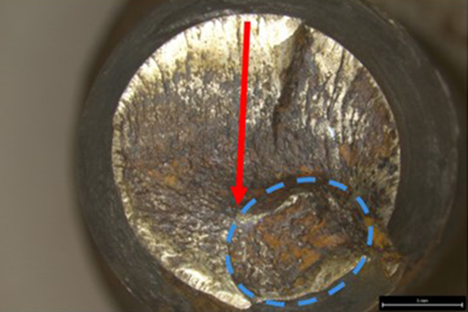
Figure 1: Fracture face of the upper portion of a recovered screw with indications of unidirectional high-cycle and low-cycle bending fatigue and a small area of overload (circled).
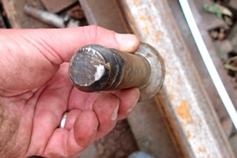
Figure 2: One of the recovered top portions of a screw with signs of historical fracture and subsequent failure by overload (bright area).