[Withdrawn] Notice number 30 (revision 3)
Updated 10 September 2025

© Crown copyright 2025
This publication is licensed under the terms of the Open Government Licence v3.0 except where otherwise stated. To view this licence, visit nationalarchives.gov.uk/doc/open-government-licence/version/3 or write to the Information Policy Team, The National Archives, Kew, London TW9 4DU, or email: psi@nationalarchives.gov.uk.
Where we have identified any third party copyright information you will need to obtain permission from the copyright holders concerned.
This publication is available at https://www.gov.uk/government/publications/carriage-of-dangerous-goods-exception-notice-30/notice-number-revision-3
The Carriage of Dangerous Goods and Use of Transportable Pressure Equipment Regulations 2009 (as amended) and The Carriage of Dangerous Goods & Use of Transportable Pressure Equipment Regulations (Northern Ireland) 2010
Notice of Recognition Notice Number 30 - Rev.3
Currently, there is no standard listed in Regulations Concerning the International Carriage of Dangerous Goods by Rail (RID) / European Agreement Concerning the International Carriage of Dangerous Goods by Road (ADR) which expressly specifies suppressor valve head assemblies designed for use in explosion protection systems.
Consequently, in accordance with the provisions of Chapter 6.2.5 of RID / ADR, the GB and NI competent authorities[footnote 1] [footnote 2], recognise technical code BR 30, dated June 2015 (annexed to this notice) for the construction and transport of suppressor valve head assemblies for use in explosion protection systems.
Reference: Technical Code BR 30, Issue 1, June 2015
Title: Explosion Suppressor Valve Head Assemblies for Use in Explosion Protection Systems, Issue 1, June 2015
Scope
Terms, definitions, and design, construction and testing methods for explosion suppressor valve head assemblies, including requirements for traceability of materials and maintenance associated production records.
A technical specification of each new design of suppressor valve head assembly as appropriate, including design drawing, design calculation (as applicable) and material details, shall be prepared by the manufacturer.
Duration
This notice has immediate effect and shall remain in force until revised or withdrawn.
Signed by:
Roh Hathlia
Head of Dangerous Goods Division Department for Transport, who has been duly authorised to sign in that behalf.
01 January 2019
Annex
Technical Code for Explosion Suppressor Valve Head Assemblies for Use in Explosion Protection Systems
Technical Code BR 30
Issue 1
June 2015
Foreword
This technical code has been prepared to meet the requirements of RID / ADR3, clause 6.2.5 in the absence of a design code listed in clause 6.2.4.1 relevant to suppressor valve head assemblies for use in explosion protection systems.
These suppressor valve head assemblies are used to provide protection against explosion risks for industrial applications. The assemblies are transported pressurised.
These suppressor valve head assemblies were approved using Article 3 of 1999/36/EC but since inclusion of these requirements in RID/ADR and ECE/TRANS/225 on 1st January 2013, there has been no mechanism to approve them
1. Scope
This technical code specifies the requirements for the design, manufacture, testing and marking of Explosion Suppressor Valve Head Assemblies subject to the provisions of the RID/ADR. Figure 1 shows a typical configuration of the assembly.
Figure 1 – Typical Explosion Suppressor Valve Head Assembly Schematic
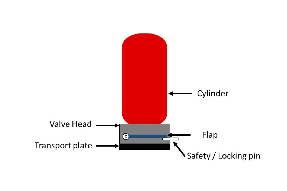
Figure 1: Diagram of a typical explosion suppressor valve head assembly schematic. A valve head is displayed with the component parts labeled as follows - cylinder, valve head, transport plate, flap, and safety locking pin.
This technical code covers explosion suppressor valve head assemblies when used in the following configuration:
- maximum valve opening diameter of 150mm
- maximum cylinder volume of 100 litre
- cylinders filled with an explosion suppressant agent and pressurised, with nitrogen, to a maximum pressure of 60 bar at 20°C
All explosion suppressor valve head assemblies are single actuation devices.
This code does not cover the approval of the cylinder or any pressure limiting devices.
2. Normative references
This technical code incorporates by dated or undated reference, provisions from other publications. These normative references are cited at the appropriate places in the text and the publications are listed hereafter.
For dated references, subsequent amendments to or revisions of any of these publications apply to this technical code only when incorporated in it by amendment or revision.
-
EN 10204 Metallic materials. Types of inspection documents.
-
ADR European Agreement concerning the International Carriage of Dangerous Goods by Road.
-
RID Regulations concerning the International Carriage of Dangerous Goods by Rail.
3. Terms and definitions
Batch
Quantity of assemblies manufactured from a single supply of material.
Material Certificate
Material documentation to EN10204:2004 Clause 3.1 for all pressure retaining materials.
Maximum working pressure
Pressure at the stated maximum operating or storage temperature, whichever is the greater; at the maximum fill ratio for the suppressant, where appropriate; as declared by the manufacturer.
Maximum operating temperature
The maximum operating temperature declared by the manufacturer, in ºC.
Maximum storage temperature
The maximum storage temperature declared by the manufacturer, in ºC.
Refurbishment
Replacement of one or more components within the pressure bearing envelope. This does not apply to the refilling of the assembly if all pressure bearing elements from the original suppressor valve head assembly remain.
Working pressure
Pressure defined by the manufacturer as the nominal operating pressure.
4. Symbols
1 bar = 0.1 MPa; 1 MPa = 1 N/mm2
5. Assessment
Conformity assessment
Conformity shall be assessed in accordance with the relevant requirements of RID/ADR section 1.8.7 and subsection 6.2.3.6.
6. Materials
General
Non-metallic materials for pressure retaining parts are not permitted.
Material Compatibility
Materials used in the pressure retaining envelope of the suppressor valve head assembly shall be compatible with each other and the explosion suppressants.
7. Requirements
Documentation
The manufacturer shall provide to the Notified Body fully dimensioned drawings of the products which shall include the specification of the components and materials used.
Material
The manufacturer shall provide as part of the design file:
- material specifications
- material certificates
- details of suppliers
Operating Conditions
The manufacturer shall declare:
- maximum and nominal working pressures
- maximum operating and storage temperatures.
The maximum operating and storage temperatures shall be not less than + 50 oC.
Pressure Limiting Devices
Where fitted, as part of the suppressor valve head assemblies for explosion protection systems, these devices shall be designed to prevent the pressure within the assembly exceeding the maximum working pressure.
Valve protection
The suppressor valve head assembly shall be protected in accordance with the requirements of Clause 4.1.6.8 of the RID/ADR.
8. Type Tests
General Requirements
Type testing shall be carried out, for each new design, under the supervision of a Notified Body.
In addition, Type testing shall be undertaken when any of the following conditions apply:
- change to manufacturing location, or
- change to manufacturing process, or
- material specifications are altered or
- changes to the design or
- the working pressure is altered.
Technical Specifications
The manufacturer shall prepare a technical specification for each design, including documentation as detailed in clause 7 and any supporting calculations.
List of Verification Tests
The following tests shall be performed for all type testing:
- connections
- pressure
- leakage
Description of Tests
Connection Threads
Container and discharge outlet connection threads shall comply with European/ International standards or standards recognised by the National Standards body in the country of approval (e.g. ISO 7-1 and EN ISO 228-1).
Pressure Test
The suppressor valve head assembly shall be tested without the pressure limiting device installed. The port shall be closed with a suitable pressure bearing plug. The suppressor valve head assembly shall not suffer any permanent deformation when tested.
The suppressor valve head assembly, in its closed position, shall be connected via the inlet to a suitable hydraulic inlet and the pressure shall be increased at a rate of 2 bar/s (+/- 1 bar/s)[footnote 4] up to 1.5 times the manufacturers declared maximum working pressure for the suppressor valve head assembly.
This pressure shall be maintained for 5 minutes (+5/-0 minutes)[footnote 5]. At the end of this period release the hydraulic pressure.
Leak Tests
The head assemblies shall not leak, and shall show no sign of damage which could impair proper function, when pressurized up to 1,5 times the working pressure.
Marking
The marking shall be non-detachable, non-flammable, permanent and legible throughout its life. The marking shall not become damaged during normal handling in manufacture and use. The minimum font size shall be 2.5mm.
The marking shall include at least the following:
- unique identifier or serial number for the complete suppressor valve head assembly
- year and month of manufacture
- mark or name of the manufacturer
- mark of Notified Body
- test pressure in bar, preceded by “PH” and followed by “BAR”.
9. Production Tests
General requirements
The manufacturer shall be technically competent and ensure that he has available the manufacturing means and processes suitable for fabricating the suppressor valve head assemblies in accordance with this technical code. The manufacturer shall operate an appropriate quality system approved by a Notified Body in accordance with clause 1.8.7 of RID/ADR. The manufacturer shall ensure that the materials and components used in the fabrication of the suppressor valve head assembly is free from any defect likely to impair its safe use.
Inspection and testing, during production
Production Pressure Testing
The manufacturer shall ensure that all suppressor valve head assemblies are tested and meet the requirements of 8.2.2. The manufacturer shall retain records of all testing in accordance with clause 10.
Production Leakage Testing
The manufacturer shall ensure that all suppressor valve head assemblies are tested and meet the requirements of 8.2.3. The manufacturer shall retain records of all testing in accordance with clause 10.
Traceability
Pressure retaining parts
The identification and the control of the materials for all pressure-retaining parts shall be such as to ensure that the materials used in manufacture meets the specification of the design.
The serial numbers of all components used in the build-up of the pressure bearing envelope of the suppressor valve head assembly shall be recorded. For each complete assembly, a record of the component elements shall be maintained which records the parts/components together with the drawing references, material certificates and instructions. The pressure bearing components shall be covered by EN 10204 3.1 certificates.
Pressure Limiting Device
Where pressure limiting devices are used certificates of conformity shall be obtained and records of the serial numbers of the devices shall be maintained as part of the build-up of records for each suppressor valve head assembly.
Refurbishment
The manufacturer shall test refurbished suppressor valve head assemblies to clause 9.2 and retain records in accordance with clause 10.
10. Records
Manufacturers shall comply with clause 1.8.7.1.5 of RID/ADR.
-
Regulation 26 of The Carriage of Dangerous Goods and Use of Transportable Pressure Equipment Regulations 2009 (as amended) provides for the GB competent authority to perform those functions that are identified in ADR, RID and ADN as being the functions of a competent authority ↩
-
Regulation 22 of The Carriage of Dangerous Goods and Use of Transportable Pressure Equipment Regulations 2010 (as amended) provides for the Northern Ireland competent authority to perform those functions that are identified in ADR, RID and ADN as being the functions of a competent authority. ↩
-
Clause 5.5.2 (para 2) - BS EN 12094-4:2004 Fixed firefighting systems. Components for gas extinguishing systems. Requirements and test methods for container valve assemblies and their actuators ↩
-
Clause 5.5.2 (para 3) - BS EN 12094-4:2004 Fixed firefighting systems. Components for gas extinguishing systems. Requirements and test methods for container valve assemblies and their actuators ↩