Draft Ecodesign for Energy-Related Products (Industrial Fans) Regulations 2026 (HTML)
Updated 23 October 2026
Applies to England, Scotland and Wales

© Crown copyright 2026
This publication is licensed under the terms of the Open Government Licence v3.0 except where otherwise stated. To view this licence, visit nationalarchives.gov.uk/doc/open-government-licence/version/3 or write to the Information Policy Team, The National Archives, Kew, London TW9 4DU, or email: psi@nationalarchives.gov.uk.
Where we have identified any third party copyright information you will need to obtain permission from the copyright holders concerned.
This publication is available at https://www.gov.uk/government/consultations/improving-standards-for-industrial-fans/draft-ecodesign-for-energy-related-products-industrial-fans-regulations-2026-html
No.
The Ecodesign for Energy-Related Products (Industrial Fans) Regulations 2026
Made ***
Laid before Parliament ***
Coming into force ***
The Secretary of State makes these Regulations in exercise of the powers conferred by regulations 22 and 24(2) of the Ecodesign for Energy-related Products Regulations 2010(a)[footnote 1] (the “2010 Regulations”).
For the purposes of paragraph (1) of regulation 22 of the 2010 Regulations, the Secretary of State considers that the matters set out in paragraphs (2) and (6) of regulation 22 are satisfied. The Secretary of State has complied with paragraph (4) of regulation 22 of the 2010 Regulations.
Citation, commencement and extent
-
1.—(1) These Regulations may be cited as the Ecodesign for Energy-Related Products (Industrial Fans) Regulations 2026.
- (2) These Regulations extend to England and Wales and Scotland and come into force on [laying date plus 22 days].
Interpretation
-
2. In these Regulations—
- the “2010 Regulations” means the Ecodesign for Energy-Related Products Regulations 2010(b)[footnote 2];
- “air circulating fan” means a fan—
- (a) that is unconnected to any ducting,
- (b) the stator of which cannot be connected to ducting,
- (c) that is used for moving air within a space, such as a room or open-air area,
- (d) that has no partition between inlet and outlet and the air circulates freely from outlet to inlet,
- (e) that operates against zero external pressure,
- (f) that is not a jet fan and is not marketed as such,
- (g) that has a measurement arrangement as per measurement category E, within the meaning given by paragraph 1 of Schedule 1, and
- (h) for which performance information at zero Pa is provided on the manufacturer’s website, catalogues, brochures, technical documentation, or other relevant means;
- “axial fan” means a fan with a fan flow angle less than 20° (see paragraph 7 of Schedule 2);
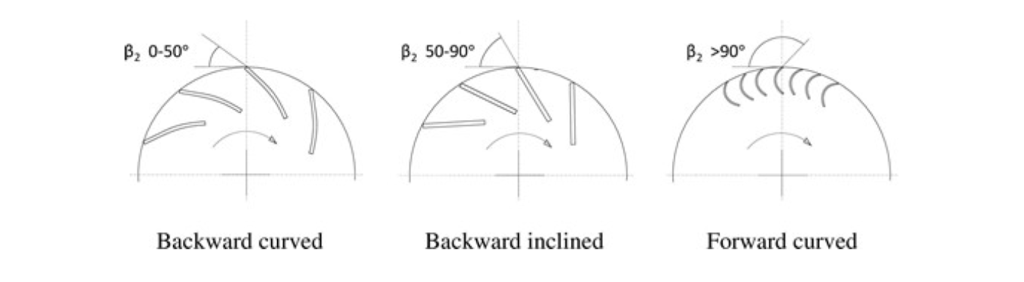
- “backward curved centrifugal fan” means a centrifugal fan with a fan blade angle (β2) greater than 0° and less than or equal to 50° (see paragraph 8 of Schedule 2);
- “backward inclined centrifugal fan” means a centrifugal fan with a fan blade angle (β2) greater than 50° and less than or equal to 90° (see paragraph 8 of Schedule 2);
- “best efficiency point” and “BEP” mean the best energy efficiency point for fan operation, determined at inherent speed;
- “centrifugal blade angle” means the fan blade angle (β2) of a centrifugal fan, expressed in degrees, determined in accordance with paragraph 8 of Schedule 2;
- “centrifugal fan” means a fan with a flow angle greater than or equal to 70° (see paragraph 7 of Schedule 2);
- “cross flow fan” means a fan in which the gas path through the impeller is in a direction essentially at right angles to its axis both entering and leaving the impeller at its periphery;
- “declared values” means the values provided by the manufacturer, importer or authorised representative(a)[footnote 3] for the stated, calculated or measured technical parameters in accordance with regulation 6, for the verification of compliance by the market surveillance authority(b)[footnote 4];
- “diffuser” means a device that influences the performance of a fan through static recovery;
- “direct drive” means a driving arrangement for a fan where the impeller is fixed to the shaft of the motor, either directly or with a coaxial coupling, and where the impeller speed is identical to the motor’s rotational speed;
- “electric input power” (Pe), in W, means the electric input power at BEP or measured thrust, measured at main terminals of the motor or, when present, of variable speed drive;
- “equivalent model” means a model that has the same technical characteristics relevant for the technical information to be provided, but which is placed on the market or put into service by the same manufacturer, importer or authorised representative as another model with a different model identifier;
- “fan” means a rotary-bladed machine—
- (a) which receives energy and utilises it by means of one or more impellers to maintain a continuous flow of air or other gas passing through it;
- (b) with a specific ratio lower than 1.1;
- (c) with an output air velocity lower than 65 m/s;
- (d) which can be of the following categories—
- (i) axial,
- (ii) centrifugal,
- (iii) cross flow,
- (iv) mixed flow, or
- (v) jet;
- (e) which is made of at least an impeller, a motor and a stator,
- and includes any other significant elements that are supplied with the fan;
- “fan flow angle” means the angle between incoming and outgoing gas flow direction of the fan impeller, expressed in degrees, calculated in accordance with paragraph 7 of Schedule 2;
- “forward curved centrifugal fan” means a centrifugal fan with a fan blade angle (β2) greater than 90° (see paragraph 8 of Schedule 2);
- “impeller” means the rotating part of a fan that is imparting energy into the gas flow (also known as the fan wheel);
- “inherent speed” means—
- (a) in the case of fans with a variable speed drive, or intended to be used with a
variable speed drive—
- (i) the maximum speed achieved by the fan, or
- (ii) the speed at which the efficiency is declared by the manufacturer, provided that the speed is in line with safe operation and the intended use of the fan;
- (b) where the motor is a multiple speed motor, the highest speed made available to the customer;
- (c) in any other case, the rotation speed of the fan impeller when the fan is operated at its nominal voltage and frequency;
- (a) in the case of fans with a variable speed drive, or intended to be used with a
variable speed drive—
- “inlet cone” (also known as venturi inlet, inlet bell or inlet radius) means a device that steers the air into an impeller and reduces the vena contracta and turbulence that would occur at the entrance of the impeller;
- “inlet or outlet guide vanes” means vanes, whether adjustable or not, positioned—
- (a) before an impeller, to guide the gas stream towards the impeller, or
- (b) after the impeller, to guide the gas stream from the impeller;
- “jet fan” means an axial, centrifugal or radial fan that—
- (a) produces a high velocity jet of air in a space (thrust), unconnected to any ducting, where the jet of air induces movement of the surrounding air, creating an overall air flow through the space, and
- (b) is designed for operation with open inlets and outlets rather than operating against pressure, including radial and centrifugal fans with an angle entrance of less than or equal to 90° to the outlet;
- “measured thrust” and “Tm” means the jet fan thrust measured, in N, assessed according to measurement category E, within the meaning given by paragraph 1 of Schedule 1, and converted to the density of 1.2;
- “mixed flow fan” means a fan with a flow angle greater than or equal to 20° and less than 70° (see paragraph 7 of Schedule 2);
- “model identifier” means the code (usually alphanumeric) which distinguishes a specific product model from other models with the same trademark or the same manufacturer’s, importer’s or authorised representative’s name;
- “motor” means a device that converts electrical input power into mechanical output power in the form of a rotation with rotational speed and torque that depends on factors including the frequency of the supply voltage and the number of poles of the motor as applicable;
- “multiple speed motor” means a motor of which the rotating speed can be varied by energising different motor windings;
- “protective guard” means a grid placed at the fan inlet or outlet designed to prevent foreign bodies or human body parts from reaching the moving parts;
- “significant elements” means the elements of a fan that contribute to the continuous
conversion of electric power into air volume flow rate and pressure, or that influence the
efficiency of that conversion, as follows—
- (a) impeller, including all rotating elements that have an aerodynamic influence;
- (b) motor;
- (c) stator
- (d) other stationary aerodynamic elements that have an aerodynamic influence,
including—
- (i) inlet cone;
- (ii) inlet or outlet guide vanes;
- (iii) diffuser;
- (e) other stationary elements that have an aerodynamic influence, including—
- (i) mechanical transmission (aerodynamic influence and influence on efficiency);
- (ii) electric transmission (aerodynamic influence and influence on efficiency), such as cable conduits, frequency inverter, variable speed drive, terminal box, AC/DC converter;
- (iii) structural components that hold the assembly in place and may interfere with the airflow, such as brackets supporting the motor or the bearings;
- “spare part fan” means a fan intended to replace a corresponding fan that is integrated into a product;
- “specific ratio” means the stagnation pressure measured at the fan outlet divided by the stagnation pressure at the fan inlet at BEP;
- “stagnation pressure” (psg), in Pa, means the pressure measured at a point in a flowing gas if it were brought to rest via a process where there is no transfer of heat or matter;
- “stator” means the stationary part of a fan that interacts with the air stream passing through the impeller and—
- (a) includes any element between defined fan inlet and outlet sections that may increase the fan efficiency, and
- (b) excludes any element other than the fan between defined fan inlet and outlet sections that may decrease the fan efficiency;
- “transmission” means a driving arrangement for a fan that is not direct drive, including using a belt drive, gearbox or slipping coupling;
- “variable speed drive” and “VSD” mean an electronic power converter, integrated or functioning as a separate unit, that continuously adapts the electric power supplied to a single motor or multiple motors, in order to control the mechanical power output of the motor or motors according to the torque-speed characteristic of the load driven by the motor or motors, by adjusting the power supply to a variable frequency and voltage supplied to the motor or motors—
- (a) including electronically commutated motors’ internal controllers;
- (b) excluding variable voltage controllers where only the supply voltage for the motor or motors is varied, and including all integrated protection devices and auxiliaries.
Application
-
3.—(1) These Regulations apply to fans with an electric input power greater than or equal to 125 W and less than or equal to 500 kW at their best efficiency point, including where they are integrated into other products.
- (2) These Regulations do not apply to—
- (a) fan impellers mounted on the shaft of motors with the sole purpose of cooling the motors themselves;
- (b) fans integrated into laundry and washer-dryers with maximum electric input power lower than or equal to 3 kW;
- (c) fans integrated into kitchen hoods with total maximum electric input power attributable to the fan lower than 280 W;
- (d) fans with a best efficiency point at 8000 revolutions per minute or more;
- (e) jet fans with maximum electric input power lower than 750 W.
- (3) These Regulations do not apply to fans that are specified to operate exclusively as follows and are specifically designed and marketed as such—
- (a) in potentially explosive atmospheres, as defined in regulation 2(1) of the Equipment and Protective Systems Intended for Use in Potentially Explosive Atmospheres Regulations 2016(a)[footnote 5];
- (b) for emergency use only, with regard to fire safety requirements as set out in Regulation (EU) No 305/2011 of the European Parliament and of the Council (b)[footnote 6], capable of short duration operation of one hour or more at temperatures of 300 °C and above;
- (c) in nuclear installations, as defined in Article 3, point (1), of Council Directive 2009/71/Euratom (c)[footnote 7];
- (d) in military bunkers and bomb shelters;
- (e) where operating temperatures of the gas being moved can be higher than 100 °C, or lower than – 40 °C, or both;
- (f) where operating ambient air temperatures for the motor driving the fan, if located outside the gas stream, can be higher than 60 °C, or lower than – 30 °C, or both;
- (g) with a supply voltage higher than 1 000 V AC or higher than 1 500 V DC;
- (h) for handling toxic, highly corrosive or flammable gases or vapours as referred to in Regulation (EC) No 1272/2008 of the European Parliament and of the Council (a)[footnote 8];
- (i) for material transport, characterised by handling substances with a solid particle concentration of more than 10 mg/m3 and particles with an average size of at least 0.1 mm and a hardness of at least 2 on the Mohs scale, while having an average fan blade angle of 50° to 90°;
- (j) for handling gases containing biohazardous substances of Groups 2, 3 and 4 as set out in paragraph 2 of Schedule 3 to the Control of Substances Hazardous to Health Regulations 2002(b)[footnote 9];
- (k) for handling gases containing carcinogens or mutagens as defined in Directive 2004/37/EC of the European Parliament and of the Council (c)[footnote 10];
- (l) for handling gases with a compressibility factor, rounded to the nearest second decimal, in the designated pressure and temperature range of the scope that is not equal to 1.00;
- (m) in cordless or battery-powered equipment;
- (n) in handheld equipment whose weight is supported by hand during operation;
- (o) in hand-guided mobile equipment moved while in operation;
- (p) as air circulating fans.
- (2) These Regulations do not apply to—
Ecodesign requirements
-
4.—(1) A fan must conform to the ecodesign requirements set out in paragraph 2 of Schedule 1 when it is placed on the market or put into service.
- (2) A manufacturer, importer or authorised representative of a fan must comply with paragraphs 3 to 8 of Schedule 1 (product information and resource efficiency).
Measurements and calculations
-
5. The measurements and calculations required for the purposes of compliance with, and verification of compliance with, the requirements of these Regulations, must be made—
- (a) using designated standards for fans, where available(d)[footnote 11], or other reliable, accurate and reproducible methods that take into account the generally recognised state-of-the-art methods, and
- (b) in accordance with Schedule 2.
Conformity assessment
-
6.—
- (1) A manufacturer assessing the conformity of a fan with the ecodesign requirements in Schedule 1 must use either—
- (a) the internal design control procedure set out in Part 1 of Schedule 1A to the 2010 Regulations, or
- (b) the management system procedure set out in Part 2 of that Schedule.
- (2) The technical documentation required for the conformity assessment of a fan must contain—
- (a) a copy of the declared values of parameters listed in paragraph 3(5) of Schedule 1, in the order listed in that sub-paragraph (the exact wording does not need to be repeated, information may be displayed using graphs, figures or symbols rather than text),
- (b) a copy of the declared values of the parameters of the test points in paragraph 4 of Schedule 1,
- (c) where applicable, a copy of the product information provided in accordance with paragraphs 3 to 7 of Schedule 1, and
- (d) the details and results of calculations set out in Schedule 2.
- (3) Where the information included in the technical documentation for a particular model has been obtained by either of the means mentioned in paragraph (4), the technical documentation must include—
- (a) the details of the calculation,
- (b) the assessment undertaken by the manufacturer to verify the accuracy of the calculation, and
- (c) where appropriate, the declaration of identity between the models of different manufacturers.
- (4) The means are—
- (a) from a model that has the same technical characteristics relevant for the technical information to be provided but is produced by a different manufacturer;
- (b) by calculation on the basis of design or extrapolation from another model of the same or a different manufacturer, or both.
- (5) The technical documentation must include a list of all equivalent models, including the model identifier of each equivalent model.
- (6) Where the manufacturer has used the compliance assessment options set out in paragraph 3 of Schedule 2, the technical documentation must report—
- (a) any non-significant elements removed,
- (b) any model scaling,
- (c) test conditions and calculations, and
- (d) the place where the testing is conducted.
- (7) Where these Regulations require the provision of performance curves at different speeds pursuant to paragraph 4 of Schedule 1, the technical documentation must indicate the characteristics of the speed regulation device used, and the speed used for those curves, as a percentage of the inherent speed.
- (8) A fan to which a VSD is added is not to be treated as a new fan model requiring a new conformity assessment if—
- (a) the VSD is physically located so as not to interfere with the air stream, and
- (b) the VSD can be removed from the fan for verification without damaging the fan and the VSD.
- (1) A manufacturer assessing the conformity of a fan with the ecodesign requirements in Schedule 1 must use either—
Verification procedure for market surveillance purposes
- 7. The market surveillance authority must use the verification procedure set out in Schedule 3 when verifying the compliance of a product with the requirements of these Regulations.
Circumvention
-
8.—
- (1) A manufacturer, importer or authorised representative must not place on the market or put into service a fan designed to alter its behaviour or properties when being tested in order to achieve a more favourable result for any declared value for the parameters set out in these Regulations.
- (2) The fans that must not be placed on the market or put into service by virtue of paragraph (1) include—
- (a) a fan designed to detect it is being tested by recognising the test conditions or test cycle and to automatically alter its behaviour or properties in response;
- (b) products preset to alter their behaviour or properties at the time of testing.
- (3) A manufacturer, importer or authorised representative must not prescribe specific test instructions that alter the behaviour or the properties of a fan to achieve a more favourable result for any of the declared values for the parameters set out in these Regulations.
- (4) The prohibition in paragraph (3) includes a prohibition on prescribing a manual alteration of a fan in preparation for a test that alters the fan’s behaviour or properties compared with when it is in normal use and operated by the end-user.
- (5) A manufacturer, importer or authorised representative must not place on the market or put into service a fan designed to alter its behaviour or properties within a short period of being put into service in a way that worsens any declared value for the parameters set out in these Regulations.
- (6) [A manufacturer, importer or authorised representative must ensure that any software or firmware update does not worsen any declared value for a parameter set out in these Regulations when measured using the testing method applicable at the time of the fan being placed on the market or put into service.
- (7) A manufacturer, importer or authorised representative must ensure that rejecting any software or firmware update does not result in any change of any declared value for a parameter of a fan set out in these Regulations when measured using the testing method applicable at the time of the product being placed on the market or put into service.]
Review
-
9. The Secretary of State must, before [date to be inserted]—
- (a) evaluate these Regulations, taking into account the speed of technological progress, and
- (b) publish a report stating whether or not in their opinion these Regulations should be amended.
Transitional provisions
-
10.—
- (1) The requirements of these Regulations are deemed to be met in relation to a fan
which—
- (a) is placed on the market or put into service before [laying date plus 6 months], and
- (b) complies with Regulation (EU) 327/2011(a)[footnote 12] as it had effect immediately before [laying date plus 22 days].
- (2) The requirements in Schedule 1 are deemed to be met in relation to a fan—
- (a) which is integrated, or placed on the market exclusively to be integrated, into another product,
- (b) which is placed on the market before 24th July 2027,
- (c) which meets the requirements of Annex 1 to Regulation (EU) No 327/2011 as it had effect immediately before [laying date plus 22 days], using the calculation methods in Annex 2 to that Regulation, and that compliance is verifiable by the market surveillance authority in accordance with Annex 3 to that Regulation, in line with the fan’s declaration of conformity, and
- (d) the first unit of the model of which was placed on the market before 24th July 2026.
- (3) If the conditions set out in paragraph (5) are satisfied, the requirements in Schedule 1 are deemed to be met in relation to a spare part fan that—
- (a) is placed on the market before 24th July 2037, and
- (b) replaces a fan—
- (i) integrated into another product, and
- (ii) placed on the market before 24th July 2026.
- (4) If the conditions set out in paragraph (5) are satisfied, the requirements in Schedule 1 are deemed to be met in relation to a spare part fan that—
- (a) is placed on the market before 24th July 2037,
- (b) replaces a fan integrated into another product, and
- (c) meets the requirements in sub-paragraphs (a) to (d) of paragraph (2).
- (5) The conditions are—
- (a) in the range of products offered by the manufacturer, importer or authorised representative, there is no replacement fan that is fit to be integrated into the product in question which is compliant with these Regulations,
- (b) the manufacturer, importer or authorised representative complies with the information requirements set out in paragraph (6), and
- (c) the fan meets the requirements set out in point 2 of Annex 1 to Regulation (EU) No 327/2011 that were applicable at the date of placing on the market of the fan that it is intended to replace, using the calculation methods in Annex 2 to that Regulation, and that compliance is verifiable by the market surveillance authority in accordance with Annex 3 to that Regulation.
- (6) The product information requirements are—
- (a) the product information specified in paragraph (7) must be indicated in a clear and visible manner in the following places in relation to a spare part fan—
- (i) the packaging or, in the absence of packaging, the product itself,
- (ii) the technical data sheet or user manual supplied with the fan, and
- (iii) with any product information relating to the fan that is available online and in any catalogue;
- (b) the technical data sheet or user manual supplied with a spare part fan must include—
- (i) the manufacturer’s name, registered trade name or registered trademark, and the address at which the manufacturer can be contacted;
- (ii) the model identifier and, where appropriate, other codes and marks sufficient for the product to be unequivocally and easily identified;
- (iii) information relevant for facilitating disassembly, recycling or disposal at end-of-life
- (iv) information relevant to minimising impact on the environment and ensuring optimal life expectancy as regards installation, use and maintenance of the fan;
- (v) information about the product or products in which the spare part fan is to be integrated.
- (a) the product information specified in paragraph (7) must be indicated in a clear and visible manner in the following places in relation to a spare part fan—
- (7) The specified product information is—
- “This fan does not meet the performance requirements of [the Ecodesign for Energy-Related Products (Industrial Fans) Regulations 2026 (S.I. 2026/xxx)] with regard to ecodesign requirements for fans driven by motors with an electric input power between 125 W and 500 kW, and can only be used to replace a corresponding existing fan placed on the market before 24 July 2026 and integrated into a product, because no compliant fan is fit to be used as a replacement”.
- (8) Fans placed on the market before 24 July 2027 are not required to comply with the requirements in paragraph 4 of Schedule 1.
- (1) The requirements of these Regulations are deemed to be met in relation to a fan
which—
Consequential amendments
-
11. In the 2010 Regulations, in Schedule 1, in paragraph 4, in the table, for item 15 substitute—
- “15. A fan driven by a motor with an electric input power between 125W and 500kW [The Ecodesign for Energy-Related Products (Industrial Fans) Regulations 2026]”.
Revocation
- 12. Regulation (EU) No 327/2011 is revoked.
Schedules
SCHEDULE 1: Ecodesign requirements for industrial fans
(Regulation 4)
Interpretation of Schedule 1
-
1. In this Schedule—
- “custom fan” means a fan—
- (a) that has—
- (i) a custom design with respect to one or more of the significant elements for a specific customer, a specific contract or both, and
- (ii) has an operating point or range specified by the customer, the contract or both,
- (b) details of which are not presented in catalogues, online media or general selection tools, and
- (c) the performance details of which are specific to the application and the customer, the contract or both;
- (a) that has—
- “dual use fan” means a fan designed for both ventilation under normal conditions and emergency use as set out in regulation 3(3)(b);
- “efficiency category” means the fan gas output energy form used to determine the fan
efficiency or jet fan efficiency, which for all fans except jet fans is—
- (a) “static” efficiency, if the fan gas power (Pu) has been determined with the fan static pressure, or
- (b) “total” efficiency, if the fan gas power (Pu) has been determine with the fan pressure;
- “efficiency grade” means a parameter in the calculation of the minimum fan efficiency of electric input power at its BEP or at Tm (expressed as parameter ‘N’ in the calculation of the fan efficiency);
- “fan efficiency” (η) means the ratio of the fan gas power (Pu) output and the electric input power (Pe), both expressed in W and determined at BEP, multiplied with power conversion correction (Cp), part load compensation (Cc) and guard compensation (Cguard), which is—
- (a) “static” efficiency, if the fan gas power (Pu) has been determined with the fan static pressure, or
- (b) “total” efficiency, if the fan gas power (Pu) has been determined with the fan pressure, in accordance with paragraph 9 of Schedule 2;
- “fan gas power” (Pu), in W, means the product of the volume flow rate (qv), in m3/s, and the applicable pressure difference between fan inlet and outlet (Δp) (fan pressure or fan static pressure), in Pa, both determined at BEP, which is—
- (a) “static” fan gas power, if the fan gas power has been determined with the fan static pressure, or
- (b) “total” fan gas power, if the fan gas power has been determined with the fan pressure;
- “fan pressure” (pf), in Pa, means—
- (a) the difference between the stagnation pressures at the fan outlet and the fan inlet, or
- (b) when compressibility phenomenon is not a factor, the difference between the total pressures at the fan outlet and the fan inlet,
- (it is the directional force per unit surface area exerted at the fan outlet and is typically assessed by measuring the stagnation pressure in a cylindrical hole of appropriate geometry and dimensions facing the direction of the gas flow);
- “fan static pressure” (pfs), in Pa, means—
- (a) the difference between the static pressure at the fan outlet and the stagnation pressure at the fan inlet, or
- (b) when the compressibility phenomenon is not a factor, the difference between the static pressure at the fan outlet and the total pressure at the fan inlet,
- (it is the omnidirectional force per unit surface area exerted at the fan outlet and is typically assessed by measuring the stagnation pressure in a cylindrical hole of appropriate geometry and dimensions, in duct wall or appropriate measurement instrument perpendicular to the direction of the gas flow);
- “guarantee” means any undertaking by the manufacturer, importer or authorised
representative to the consumer, to—
- (a) reimburse the price paid, or
- (b) replace, repair or handle fans in any way if they do not meet the specifications set out in the guarantee statement or in the relevant advertising;
- “guard compensation” (Cguard) means a correction factor, as determined according to paragraph 9 of Schedule 2, that may be applied when calculating fan efficiency or jet fan efficiency where the fan is equipped with permanently fitted protective guards that cannot be removed without making the fan inoperable;
- “impeller diameter” (Dimpeller), in mm, means the maximum diameter measured over the tips of the blades of the impeller;
- “jet fan efficiency” (ηr(T)) means the fan gas power output derived from the measured thrust of a jet fan divided by the electric input power (Pe), multiplied with correction factors for power conversion Cp, part load compensation Cc and guard compensation Cguard, in accordance with paragraph 10 of Schedule 2;
- “low noise fan” means an axial fan with an electric input power of 10 kW or more with a maximum characteristic noise emission value (L) less than or equal to 32 dB(A) at BEP, in accordance with paragraph 11 of Schedule 2;
-
“manufacturer-authorised professional repairer” means a professional repairer authorised by the manufacturer, importer or authorised representative to repair safety critical fans placed on the market by the manufacturer, importer or authorised representative;
- “measurement category” means a test, measurement or usage arrangement that defines the inlet and outlet conditions of the fan being tested;
- “measurement category A” means an arrangement where a fan is measured with free inlet and outlet conditions, and a partition between inlet and outlet zone;
- “measurement category B” means an arrangement where the fan is measured with free inlet and with a duct fitted to its outlet, and a partition between inlet and outlet zone;
- “measurement category C” means an arrangement where the fan is measured with a duct fitted to its inlet and free outlet conditions, and a partition between inlet and outlet zone;
- “measurement category D” means an arrangement where the fan is measured with a duct fitted to its inlet and outlet, and a partition between inlet and outlet zone;
- “measurement category E” means an arrangement where the fan is measured with free inlet and outlet conditions, and without a partition between inlet and outlet zone;
- “minimum fan efficiency” (ηmin) means the fan efficiency to be achieved in order to meet the requirements, determined in accordance with paragraph 2, using the applicable integer N of the efficiency grade and the electric input power (Pe) of the fan expressed in kW at its BEP;
- “part load compensation” (Cc) means a correction factor for part load, as determined according to paragraph 9 of Schedule 2;
- “power conversion correction” (Cp), means a correction factor for power conversion losses, as determined according to paragraph 9 of Schedule 2;
- “professional repairer” means an operator or undertaking which provides services of repair and professional maintenance of fans;
- “proprietary tool” means a tool that is—
- (a) not commonly available, and
- (b) specifically designed for a function that cannot be achieved by a commonly available tool safely, reliably or safely and reliably;
- “reversible fan” means a fan capable of reaching at least 80% of the nominal forward volume flow rate in the reverse direction;
- “safety critical fan” means a fan that has been designed, verified, certified and manufactured under the scope of either the Regulation (EU) No 305/2011(a)[footnote 13] or the Equipment and Protective Systems Intended for Use in Potentially Explosive Atmospheres Regulations 2016(b)[footnote 14] relating to equipment and protective systems intended for use in potentially explosive atmospheres;
- “spare part” means a separate part that can replace a part with the same or similar function in a fan;
- “specific speed” (σΒΕΡ ) means the ratio between volume flow rate (qv) and fan pressure (pf) as dimensionless characteristic number determined at BEP, paragraph 12 of Schedule 2;
- “total pressure” (ptot), in Pa, means the pressure calculated from—
- (a) the pressure measured with respect to absolute zero pressure, in Pa (absolute pressure) (p), and
- (b) the pressure calculated from the velocity and the density, in Pa (dynamic pressure) (pd);
- “volume flow rate” (qv), in m3/s, means the gas volume displaced per unit of time by the fan (derived from the mass flow rate, typically with standard air with a density ρ at default 1200 kg/m3);
- “wearing parts (sacrificial elements)” means parts that are intentionally designed to wear, for the fan to meet the requirements of its intended use (for example, where a fan is used in an abrasive environment the fan can quickly become damaged by the abrasion. Some parts are designed as sacrificial elements to protect other critical areas and are designed to be replaced more frequently).
- “custom fan” means a fan—
Minimum fan efficiency requirements
-
2.—
- (1) The requirements for minimum fan efficiency are set out in sub-paragraphs (2) to (5), with the values of the minimum efficiency grade (N) for the purposes of sub paragraphs (2) to (3) determined in accordance with sub-paragraphs (6) to (8).
- (2) Fans, other than jet fans, cross flow fans and fans referred to in sub-paragraph (5), must have a fan efficiency (η) equal to or larger than the minimum fan efficiency (ηmin), which is a function of the electric input power (Pe) in kW and minimum efficiency grade (N) in accordance with the following equations—
- (a) for fans with Pe less than 10 kW, ηmin = 4.56 ln(Pe) – 10.5 + N (%);
- (b) for fans with Pe greater than or equal to 10 kW, ηmin = 1.1 ln(Pe) – 2.6 + N (%).
- (3) Jet fans must have a jet fan efficiency (ηr(T)) equal to or larger than the minimum jet fan efficiency (ηr,min), which is a function of the electric input power (Pe) in kW and minimum efficiency grade (N) in accordance with the following equations—
- (a) for jet fans with electric input power (Pe) greater than or equal to 750 W and less than 10 kW, ηr,min = 7.32 ln(Pe) – 21.25 + N (%);
- (b) for jet fans with electric input power (Pe) greater than or equal to 10 kW, ηr,min = 1.73 ln(Pe) – 8.35 + N (%).
- (4) Cross flow fans must have a minimum total fan efficiency of at least 0.21 (21 %) over the entire power range.
- (5) For centrifugal fans with—
- (a) specific speed (σΒΕΡ) less than 0.12,
- (b) electric input power (Pe) less than 10 kW,
- (c) measurement category B or D, and
- (d) efficiency category ‘total’, the minimum fan efficiency (ηmin) is a function of σΒΕΡ as follows, ηmin = 2.95 * σΒΕΡ + 0.2.
- (6) Subject to sub-paragraph (8), the values of the minimum efficiency grade (N) for fans, other than cross flow fans and fans referred to in sub-paragraph (5), are set out in Table 1 per fan type, efficiency category (static or total) and measurement category (A to E), as appropriate.
Table 1: Minimum efficiency grades
| Fan type | Measurement category | Efficiency category (pressure) | Minimum efficiency grades (N) |
|---|---|---|---|
| Axial fans | A, C | static | 50 |
| Axial fans | B, D | total | 64 |
| Forward curved centrifugal fans < 5 kW and backward inclined centrifugal fans | A, C | static | 52 |
| Forward curved centrifugal fans < 5 kW and backward inclined centrifugal fans | B, D | total | 57 |
| Other centrifugal fans | A, C | static | 64 |
| Other centrifugal fans | B, D | total | 67 |
| Mixed flow fans | A, C | static | 57 + 7 • (α –45 ) / 25 |
| Mixed flow fans | B, D | total | 67 |
| Jet fans ≥ 750 W | E | - | 50 |
- —
- (7) The minimum efficiency grade (N) for mixed flow fans must be calculated using the fan flow angle (α), in degrees rounded to the nearest integer, established in accordance with paragraph 7 of Schedule 2.
- (8) For fans with the characteristics set out in the first column of Table 2, the values of the minimum efficiency grade (N) set out in Table 1 must be multiplied by the corresponding factor in the second column of Table 2, as applicable.
Table 2
| Fan characteristics | Factor value |
|---|---|
| Dual use fans designed for both ventilation under normal conditions and emergency use as set out in regulation 3(3)(b) | 0.9 |
| Reversible fans | 0.85 |
| Low noise fans | 0.9 |
Product information requirements on fans
-
3.—
- (1) The product information requirements for fans are—
- (a) for fans other than custom fans, the requirements set out in sub-paragraphs (2), (3) and (6) to (8), and
- (b) for custom fans, the requirements set out in sub-paragraphs (4) and (6) to (8).
- (2) The free access website of the manufacturer of a fan, its authorised representative or the importer, must include the information set out in sub-paragraph (5)(a) to (o) in relation to the fan for at least the period beginning with the date on which the first unit of the model concerned is placed on the market and ending 20 years after the date on which the last unit of the model concerned is placed on the market.
- (3) The technical data sheet or user manual supplied with a fan must include the information set out in sub-paragraph (5)(a) to (o) in relation to the fan, unless—
- (a) an internet link or a QR code linking to the free access website referred to in sub-paragraph (2) is supplied with the fan, and
- (b) a pictogram as in ISO 7000:2019(a)[footnote 15] reference n°1641 is displayed next to the link or QR code.
- (4) The manufacturer, authorised representative or importer of a custom fan must provide the information listed in sub-paragraph (5)(a) to (q) in relation to the fan with any commercial offer provided to a customer (and need not be provided on a free access website).
- (5) The information is—
- (a) fan type, specifically which of the following types of fan the fan is—
- (i) axial fan,
- (ii) forward curved centrifugal fan,
- (iii) backward curved centrifugal fan,
- (iv) backward inclined centrifugal fan,
- (v) cross flow fan,
- (vi) mixed flow fan, or
- (vii) jet fan;
- (b) fan efficiency or jet fan efficiency (η or ηr(T)), either as a number rounded to the nearest third decimal, or as a percentage (with symbol ‘%’) rounded to the nearest decimal;
- (c) whether the calculation of fan efficiency or jet fan efficiency assumed use of a VSD and if so, whether the VSD is integrated in the fan or the VSD must be installed with the fan;
- (d) measurement category used to determine the fan efficiency or jet fan efficiency (A-E);
- (e) efficiency category (static or total), except for jet fans;
- (f) efficiency grade (N) at BEP or Tm, except for cross flow fans;
- (g) the electric input power (Pe) in kW, rounded to the nearest third decimal, volume flow rate (qv) in m3/h rounded to the nearest integer, or alternatively, when flow rate is greater than or equal to 0.50 m3/s in m3/s rounded to the nearest second decimal, and applicable pressure difference Δp in Pa, rounded to the nearest integer at BEP or Tm;
- (h) special characteristics, specifically any of the following that describe the fan—
- (i) dual use fan;
- (ii) reversible fan;
- (iii) low noise fan;
- (i) DC voltage lower than 100 V, with answer ‘yes’ or ‘no’;
- (j) a list of all significant elements supplied with the fan;
- (k) specific speed (σΒΕΡ), only for centrifugal fans with—
- (i) specific speed (σΒΕΡ) less than 0.12,
- (ii) electric input power (Pe) less than 10 kW,
- (iii) measurement category B or D, and
- (iv) efficiency category ‘total’;
- (l) inherent speed at BEP or Tm in rpm, rounded to the nearest integer;
- (m) the specific ratio, rounded to the nearest second decimal;
- (n) manufacturer’s name, registered trade name or registered trademark, and the address at which the manufacturer can be contacted;
- (o) the model identifier and, where appropriate, other codes and marks sufficient for the product to be unequivocally and easily identified;
- (p) information relevant to facilitating disassembly, recycling or disposal;
- (q) information relevant to minimising impact on the environment and ensuring optimal life expectancy as regards installation, use and maintenance of the fan.
- (a) fan type, specifically which of the following types of fan the fan is—
- (6) The information referred to in sub-paragraph (5)(a), (b), (d), (e) and (f) and year of manufacture must be durably marked on or near the rating plate of the fan.
- (7) If the calculation of fan efficiency or jet fan efficiency assumed use of a VSD, the wording specified in paragraph (a) or (b) that applies must be durably marked on or near the rating plate of the fan—
- (a) ‘A variable speed drive must be installed with this fan’;
- (b) ‘A variable speed drive is integrated within the fan’.
- (8) Manufacturers must provide information in the user manual relating to a fan on specific precautions to be taken when the fan is assembled, installed or maintained, including cleaning.
- (1) The product information requirements for fans are—
Information requirements on partial load or at specified duty
-
4.—
- (1) The information requirements on partial load or at specified duty are—
- (a) for all fans, other than custom fans, jet fans and fans with multiple speed motors, the requirements set out in sub-paragraphs (2) to (4);
- (b) for custom fans that are not jet fans, the requirements set out in sub-paragraphs (5) to (7);
- (c) for jet fans, the requirements set out in sub-paragraphs (8) to (11);
- (d) for fans with multiple speed motors that are not jet fans, the requirements set out in sub-paragraph (12).
- (2) For all fans, other than custom fans, jet fans and fans with multiple speed motors, the information set out in sub-paragraph (3) must be included—
- (a) on the free access website of the manufacturer of a fan, its authorised representative or the importer, and
- (b) where no internet link or QR code to that information is supplied with the fan, in the technical data sheet or user manual supplied with the fan.
- (3) The information is the partial-load operational performance of the fan described by a minimum of three performance curves including—
- (a) one at the inherent speed,
- (b) one at a lower speed of between 40 % and 50 % of the inherent speed, and
- (c) one at a speed half way between the speeds of the other two performance curves, plus or minus 10 percentage points.
- (4) For the purposes of sub-paragraph (3)—
- (a) performance curves must comprise a sufficient number of test points to permit the characteristic curve to be plotted over the normal operating range,
- (b) the information on the curves may be in digital form such as selection software or online catalogue, and
- (c) the values of volume flow, pressure, electric power, fan rotation speed and efficiency must be provided for the individual test points.
- (5) For custom fans that are not jet fans, either—
- (a) an internet link or a QR code to the information set out in (6) must be supplied with the fan with a pictogram as in ISO 7000:2019(a)[footnote 16] reference n° 1641 displayed next to the link or QR code, or
- (b) the information set out in (6)must be included in—
- (i) a commercial offer provided to a customer, or
- (ii) the technical data sheet or user manual supplied with the fan.
- (6) The information is—
- (a) for a custom fan that operates at a single specified operating point, the performance of the custom fan at that specified operating point;
- (b) for any other custom fan, the performance curve of the custom fan at the specified operating points or operating ranges.
- (7) For the purposes of sub-paragraph (6)(b)—
- (a) a performance curve shall comprise a sufficient number of test points to permit the characteristic curve to be plotted over the normal operating range, and
- (b) the values of volume flow, pressure, electric power and efficiency must be provided for the individual test points.
- (8) For jet fans that are not custom fans, the information set out in sub-paragraph (10) must be included—
- (a) on the free access website of the manufacturer of a fan, its authorised representative or the importer, and
- (b) where no internet link or QR code to that information is supplied with the fan, in the technical data sheet or user manual supplied with the fan.
- (9) For jet fans that are custom fans, the information set out in sub-paragraph (10) must be provided with any commercial offer provided to a customer (and need not be provided on a free access website).
- (10) The information is the partial-load operational performance of the fan as follows—
- (a) for jet fans with a single speed motor, no partial load information;
- (b) for jet fans without variable speed drives or not intended to be used with variable speed drives, but fitted with a multiple fixed speed motor, performance at the inherent speed and at the lower speed settings;
- (c) for jet fans with a variable speed drive or intended to be used with a variable speed drive, performance at—
- (i) the inherent speed,
- (ii) 30% of the inherent speed, and
- (iii) 50% of the inherent speed.
- (11) For the purposes of sub-paragraph (10), for each operating point, the information must include at least thrust, electric input power, rotational speed and efficiency.
- (12) For fans with multiple speed motors that are not jet fans—
- (a) if the fan is not a custom fan, sub-paragraphs (2) to (4) apply as if the information in sub-paragraph (3) were the performance curve of the custom fan at the motor’s inherent speed and the motor’s minimum speed;
- (b) if the fan is a custom fan, sub-paragraphs (5) to (7) apply as if the information in sub-paragraph (6) were the performance curve of the custom fan at the motor’s inherent speed and the motor’s minimum speed.
- (1) The information requirements on partial load or at specified duty are—
Resource efficiency requirements
-
5.—
- (1) This paragraph applies in relation to fans that are not—
- (a) custom fans for which spare part availability is addressed in the contract;
- (b) fans that are specifically designed and marketed exclusively to be integrated in specific energy-related products in relation to which there is an applicable implementing measure(a)[footnote 17] which includes ecodesign requirements with respect to spare part availability.
- (2) For all models, units of which are placed on the market on or after [laying date plus 22 days], manufacturers, importers or authorised representatives of fans, other than safety critical fans, must make available to professional repairers for the relevant period at least the following spare parts, if part of the fan, as individual elements or in an assembly when integrated as originally supplied—
- (a) motors of which the rated power is lower than 10 kW;
- (b) motor brushes;
- (c) impellers;
- (d) stator elements;
- (e) mechanical drive components;
- (f) variable speed drives;
- (g) sensors;
- (h) wearing parts (sacrificial elements);
- (i) joints and fixtures required to install these spare parts;
- (j) fan bearings;
- (k) motor bearings when the fan is integrated with the motor above 1 kW.
- (3) For all models, units of which are placed on the market on or after [laying date plus 22 days], manufacturers, importers or authorised representatives of safety critical fans, must make available to manufacturer-authorised professional repairers for the relevant period at least the following spare parts, if part of the fan, as individual elements or in an assembly when integrated as originally supplied—
- (a) motors of which the rated power is lower than 10 kW;
- (b) motor brushes;
- (c) impellers;
- (d) stator elements;
- (e) mechanical drive components;
- (f) variable speed drives;
- (g) sensors;
- (h) wearing parts (sacrificial elements);
- (i) joints and fixtures required to install these spare parts;
- (j) fan bearings;
- (k) motor bearings when the fan is integrated with the motor above 1 kW.
- (4) The manufacturer, importer or authorised representative must—
- (a) no later than the beginning of the relevant period, publish, on a website which, subject to sub-paragraph (5), is accessible to the public without charge, the list of spare parts referred to in whichever of sub-paragraphs (2) or (3) applies to that product and the procedure for ordering them, and
- (b) ensure that the information referred to in paragraph (a) remains accessible throughout the relevant period.
- (5) For safety critical fans, the website providing the list of spare parts, and the procedure for ordering them, may be restricted by username and password to manufacturer authorised professional repairers.
- (6) During the relevant period, the manufacturer, importer or authorised representative must ensure the delivery of the spare parts with the following timeframes—
- (a) where a contract exists between the manufacturer and the end user of the fan, as specified in the contract;
- (b) where no such contract exists, as specified in the product information of the fan and made available on free access websites;
- (c) where no contract exists and a timeframe is not specified in accordance with paragraph (b), no later than 6 weeks after the manufacturer, importer or authorised representative receives an order.
- (7) Manufacturers, importers or authorised representatives of fans must ensure that the spare parts mentioned in sub-paragraphs (2) and (3) can be replaced without permanent damage to the product.
- (8) When manufacturers, importers or authorised representatives of fans make available software and firmware updates, these must be available for a minimum of ten years after the last unit of the model to which the update relates is placed on the market, and these software and firmware updates must be provided free of charge.
- (9) In this paragraph and paragraphs 6 and 8, “the relevant period” is the period starting with whichever is later of—
- (a) 24th July 2028, and
- (b) the last day of the period of two years beginning with the date on which the first unit of the model is placed on the market,
- and ending with the last day of the period of ten years beginning with the date on which the last unit of the model is placed on the market.
- (1) This paragraph applies in relation to fans that are not—
Access to repair information
-
6.—(1) During the relevant period (see paragraph 5(9)) a manufacturer, importer or authorised representative of fans must make the fan repair information available to professional repairers in accordance with paragraphs (2) to (8).
- (2) The website of the manufacturer, importer or authorised representative must set out the process for professional repairers to register for access to repair information.
- (3) In order to accept a request for registration for access to the information, a manufacturer, importer or authorised representative may only require the professional repairer to demonstrate that—
- (a) the professional repairer has the technical competence to repair fans and complies with the applicable law for repairers of electrical equipment in England and Wales or Scotland (as the case may be);
- (b) the professional repairer is covered by insurance covering liabilities resulting from its activity.
- (4) A manufacturer, importer or authorised representative must accept or refuse a request for registration for access to information within five working days of the date of the request.
- (5) A manufacturer, importer or authorised representative may charge reasonable and proportionate fees for access to the repair information or for receiving regular updates.
- (6) For the purposes of sub-paragraph (5), fee is reasonable if it does not discourage access by failing to take into account the extent to which the professional repairer uses the information.
- (7) Once a professional repairer is registered, the manufacturer, importer or authorised representative must give the professional repairer access to any repair information requested by the repairer, or where relevant the information for an equivalent fan model or a fan model of the same family, within one working day of the request.
- (8) The repair information that is made available must include—
- (a) the unequivocal appliance identification,
- (b) a disassembly map or exploded view allowing visualisation of at least the spare parts made available,
- (c) a technical manual with instructions for repair,
- (d) a list of necessary repair and test equipment including details of any proprietary tool required for repair,
- (e) component and diagnosis information (such as minimum and maximum theoretical values for measurements),
- (f) wiring and connection diagrams,
- (g) diagnostic fault and error codes ,including manufacturer-specific codes, where applicable,
- (h) instructions for installation of relevant software and firmware, including reset software, and
- (i) information on how to access data records of reported failure incidents stored on the product, where applicable.
- (9) For safety critical fans, the website providing the repair information may be restricted by username and password to manufacturer authorised professional repairers.
Requirements for dismantling for material recovery and recycling while avoiding pollution
- 7. Manufacturers, importers or authorised representatives must ensure that fans are designed in such a way that the materials and components referred to in Annex 7 to Directive 2012/19/EU of the European Parliament and of the Council(a)[footnote 18] can be removed with the use of commonly available tools.
Material efficiency product information requirements
-
8. During the relevant period (see paragraph 5(9)) manufacturers, importers and authorised representatives of fans must provide user and installer instructions in the form of a user manual on a website which is accessible to the public without charge, which must include the following information—
- (a) how to access professional repair services (such as internet webpages, addresses, contact details);
- (b) relevant information for ordering the spare parts made available to end-users, directly from the manufacturer or through other channels;
- (c) the minimum period during which these spare parts are available;
- (d) the minimum duration of the guarantee of the fan in years;
- (e) details of any proprietary tool required for repair;
- (f) instructions of correct installation;
- (g) instructions for maintenance;
- (h) identification of errors, the meaning of the errors and the action required, including identification of errors requiring professional assistance;
- (i) information on any implications of self-repair or non-professional repair for the safety of the user and for the guarantee.
SCHEDULE 2: Measurements and calculations
(Regulation 5)
Preliminary
-
1. In this Schedule—
- (a) the following terms have the meaning given in paragraph 1 of Schedule 1—
- (i) “efficiency category”;
- (ii) “fan efficiency”;
- (iii) “fan pressure”;
- (iv) “fan static pressure”;
- (v) “impeller diameter”;
- (vi) “volume flow rate”.
- (b) “tip speed” (utip), in m/s, means the peripheral speed of the impeller blade tips.
- (a) the following terms have the meaning given in paragraph 1 of Schedule 1—
- 2. The declared values of the parameters in paragraph 3(5) of Schedule 1 and of the parameters of the test points in paragraph 4 of Schedule 1 must be used for the calculations in this Schedule.
-
3. For the purpose of assessing compliance with the requirements of these Regulations and provided that reliable, accurate and reproducible test and calculation methods are used, the manufacturer—
- (a) may remove the elements that are not significant elements;
- (b) may conduct the tests with the geometrical equivalent of the stator inner surface;
- (c) if the fan is a jet fan and has an impeller diameter above 1 m, or is not a jet fan and
has an impeller diameter above 0.5 m—
- (i) may conduct the tests with a scale model of the fan and calculate the results for the real-size fan;
- (ii) may conduct the tests at a customer’s site or the manufacturer’s site.
- 4. The compliance of fans with multiple speed motors must be determined at the power and speed corresponding to the highest speed made available to the customer.
- 5. The compliance of fans of which the blade pitch angle can be adjusted must be determined using the least favourable pitch configuration made available to the customer.
-
6. If the designated standards that apply to a fan specify that the test results are to be corrected—
- (a) the test results must be corrected as specified in those standards (to produce values reflecting standard air conditions and, when applicable, also the applicable inherent speed), and
- (b) the details of such corrections must be provided in the technical documentation.
Fan flow angle
- 7. The fan flow angle (α) is calculated as the average value of angles α1 and α2 following the formula:

- where—
- “α1” is the angle to the direction of the rotational axis of the tangent at the hub at the intersection of the blade trailing edge with the hub;
- “α2” is the angle to the direction of the rotational axis of the tangent at the shroud or at the outer diameter of the blade at the intersection of the blade trailing edge with the shroud or with the outer diameter of the blade, given that, if the hub, the shroud or both are not axisymmetric, angles α1 and α2 are the average values in circumferential direction.
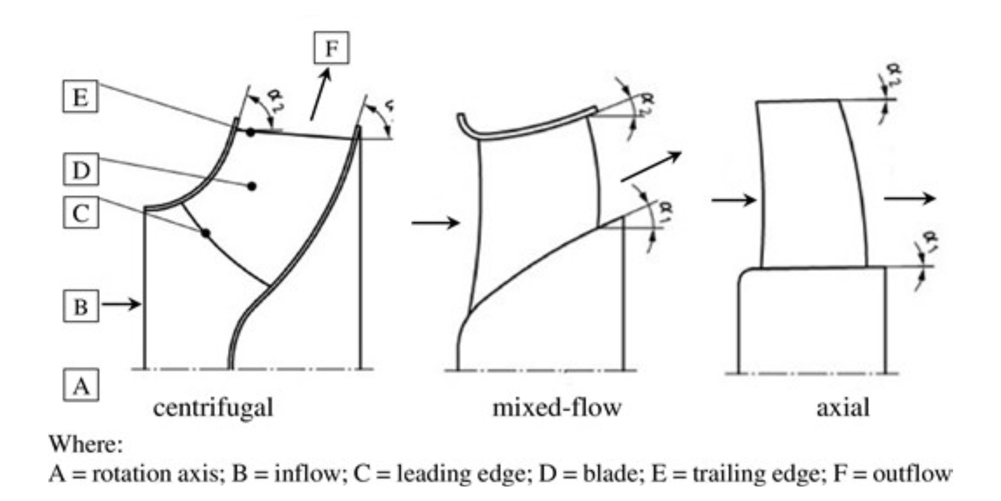
Centrifugal blade angle
-
8.—
- (1) The centrifugal blade angle (β2) is the angle between the tangent to the outer circumference of the outer circle, as defined by the trailing edge of the blades, and a line bisecting the trailing edge of the blade.
- (2) To account for blade designs that have a rapid change of angle at the trailing edge, the angle is the arithmetic mean along 50 % of the trailing length of the blade.
- (3) The trailing edge of the blade is the edge at the tip of the blade at the outlet of the impeller.
Fan efficiency
- 9. For fans other than jet fans, the fan efficiency is caculated as follows—

- where—
- “Cp” is a correction factor for power conversion losses with a value of 0.9 for fans equipped with a DC motor with a rated voltage lower than 100 V when the converter transforming AC into DC is not part of the fan, and otherwise 1.0;
- “Cc” is a correction factor for part load compensation with one of the following values, as a function of the electric input power (Pe) (expressed in kW)—
- (a) for a fan without a variable speed drive, 1;
- (b) for a fan with a variable speed drive and electric input power (Pe) greater than or equal to 5 kW and where this variable speed drive is included in the fan conformity assessment, 1.04;
- (c) for a fan with a variable speed drive and electric input power (Pe) less than 5 kW and where this variable speed drive is included in the fan conformity assessment, 1 + 0.0812 (Pe)-0.5;
- “Cguard” is a correction factor for guard compensation that may be applied when calculating fan efficiency in case the fan is equipped by permanently fitted protective guards that cannot be removed without making the fan inoperable, with one of the following values—
- (a) for a fan without a protective guard, with removable protective guard, or a protective guard with opening, e, greater than 30 mm, 1;
- (b) for a fan equipped with a protective guard with opening, e, greater than 20 mm and less than or equal to 30 mm, 1 + (30-e) · 0.004;
- (c) for a fan equipped with a protective guard with opening, e, greater than 10 mm and less than or equal to 20 mm, 1.04 + (20-e) · 0.0035;
- (d) for a fan equipped with a protective guard with opening, e, greater than 8 mm and less than or equal to 10 mm, 1.075 + (10-e) · 0.0375;
- (e) for a fan equipped with a protective guard with opening, e, less than or equal to 8 mm, 1.15, where “e” is the dimension of the opening, corresponding to the side of a square opening, the diameter of a round opening and the narrowest dimension of a slot opening, as defined in section 4.2.4.1 of standard EN ISO 13857:2019(a)[footnote 19];
- “Pu” in W, is the product of the volume flow rate (qv), in m3/s, and the applicable pressure difference between fan in- and outlet Δp, in Pa, both determined at BEP, following the expression—

- —
- where—
- “qv” in m3/s, is the gas volume displaced per unit of time by the fan and is derived from the mass flow rate, typically with standard air with a density (ρ) at default 1 200 kg/m3.
- where—
10. For jet fans, the jet fan efficiency (ηr(T)) is calculated as—

- where—
- “qv(T)” is volume flow rate at thrust T, in m3/s;
- “Δp(T)” is pressure difference at thrust T, in Pa;
- “ρ” is the standard air density (1.2 kg/m3);
- “A2” is the gross fan outlet area in m2;
- “Tm” is measured thrust (as defined in regulation 2);
- “Cp” “Cc” and “Cguard” have the same meaning as in paragraph 9.
Characteristic noise emission value
- 11. The characteristic noise emission value (L), in dB(A) is—

- where—
- “PWLimpeller” is impeller sound power level at BEP, in dB(A);
- “utip” is impeller tip speed at BEP, in m/s;
- “qv” is volume flow rate at BEP, in m3/s;
- “pfs” is fan static pressure at BEP, in Pa;
- “Dimpeller” is impeller diameter, in m.
Specific speed
12. The specific speed (σΒΕΡ) of centrifugal fans with electric input power (Pe) less than 10 kW, measurement category B or D and efficiency category ‘total’ is—

- where—
- “σΒΕΡ” is specific speed;
- “n” is fan speed in revolutions per second (rps);
- “ρ” is air density 1.2 kg/m3;
- “qv,BEP” is volume flow rate at BEP, in m3/s;
- “pf,BEP” is fan pressure at BEP, in Pa;
- “π” is the number pi (3.14…).
SCHEDULE 3: Verification procedure for market surveillance purposes
(Regulation 7)
-
1. In this Schedule the following terms have the meaning given in paragraph 1 of Schedule 1—
- (a) “efficiency category”;
- (b) “efficiency grade”;
- (c) “fan efficiency”;
- (d) “fan pressure”;
- (e) “fan static pressure”;
- (f) “impeller diameter”;
- (g) “low noise fan”;
- (h) “measurement category B”;
- (i) “measurement category D”;
- (j) “volume flow rate”.
- 2. The verification tolerances set out in Table 3 relate only to the verification of the declared values and must not be used by the manufacturer, importer or authorised representative as an allowed tolerance to establish the values in the technical documentation or in interpreting these values with a view to achieving compliance or to communicate better performance by any means.
- 3. Where a model is not in compliance with the requirements laid down in regulation 8, the model and all equivalent models shall be considered not compliant.
-
4. As part of verifying the compliance of a fan model with the requirements laid down in these Regulations pursuant to the 2010 Regulations, the market surveillance authority must apply the following procedure—
- (a) the market surveillance authority must verify one single unit of the model;
- (b) the model and all equivalent models must be considered to comply with the requirements of these Regulations if all the following conditions are satisfied—
- (i) the declared values given in the technical documentation and, where applicable, the values used to calculate these values, are not more favourable for the manufacturer, importer or authorised representative than the results of the corresponding measurements carried out pursuant to paragraph 1(2)(b)(vii) of Schedule 1A to the 2010 Regulations;
- (ii) the declared values meet any requirements of these Regulations, and any required product information published by the manufacturer, importer or authorised representative does not contain values that are more favourable for the manufacturer, importer or authorised representative than the declared values;
- (iii) when the market surveillance authority checks the unit of the model, it complies with the product information requirements in paragraphs 3, 4, and 8 of Schedule 1 and regulation 10(5) and requirements in paragraphs 5, 6 and 7 of Schedule 1 (resource efficiency, access to repair information and requirements for dismantling), as applicable;
- (iv) when the market surveillance authority tests the unit of the model, the determined values (the values of the relevant parameters as measured in testing, corrected where applicable to standard air conditions), and the values calculated from those measurements, comply with the respective verification tolerances set out in Table 3;
- (v) the fan type determined following the application of paragraph 9(a) (b) or (c) is the same as the declared fan type.
- 5. Where the results referred to in paragraph 4(b), (i), (ii) and (iii) are not achieved, the model and all equivalent models must be considered not to comply with these Regulations.
-
6. Where the result referred to in point 4(b)(iv) or (v) is not achieved—
- (a) for models that are produced in quantities of less than 25 per calendar year including equivalent models, the model and all equivalent models must be considered not to comply with these Regulations;
- (b) for models that are produced in quantities of 25 or more per calendar year including equivalent models, the market surveillance authority must select for testing—
- (i) three additional units of the same model, or
- (ii) three additional units of one or more equivalent models.
-
7. The model must be considered to comply with the these Regulations if—
- (a) for the three units referred to in point 6(b), the arithmetical mean of the determined values, complies with the respective verification tolerances set out in Table 3, and
- (b) if the fan type determined following the application of paragraph 9(a) (b) or (c) is the same as the declared fan type, where the determined value of α, or β2, or both, means the arithmetical mean of the values determined for those three additional units
- 8. Where the result referred to in paragraph 7 is not achieved, the model and all equivalent models must be considered not to comply with these Regulations.
-
9. When the market surveillance authority verifies the correspondence between fan type, centrifugal blade angle (β2), or fan flow angle (α), or both, and the minimum efficiency grade (N) specified in Table 1, they must, for the purpose of this Schedule—
- (a) for centrifugal fans declared as backward inclined centrifugal fans, or as forward curved centrifugal fans and driven by a motor with an electric input power (Pe) less than 5 kW, use the fan type and N value corresponding to ‘other centrifugal fan’ if the determined value of β2 is less than 47°;
- (b) for centrifugal fans declared as backward inclined centrifugal fans and driven by a motor with an electric input power (Pe) greater than or equal to 5 kW, use the fan type and N value corresponding to ‘other centrifugal fan’ if the determined value of β2 is more than 93°;
- (c) for fans declared as axial fans, efficiency category ‘total’, use the fan type and N value corresponding to ‘mixed flow fans’ if the determined value of α is more than 23°;
- (d) for fans declared as axial fans or mixed flow fans, efficiency category ‘static’, use the N value directly resulting from the determined value of α.
- 10. When the market surveillance authority verifies the performance curves referred to in paragraph 3 of Schedule 1, a minimum of two declared test points for each of the characteristic curves must be tested, in line with paragraphs 4 to 9 of this Schedule, taking into account paragraphs 11 to 13. If one of the declared test points is found non-compliant, the model and all equivalent models must be considered not to comply with these Regulations.
-
11. For jet fans with an impeller diameter above 1 m and for other fans with an impeller diameter above 0.5 m, the market surveillance authority may—
- (a) undertake the verification procedure at the premises of the manufacturer, authorised representative or importer of the fan, before the fan is put into service;
- (b) do this verification using its own testing equipment.
-
12. For jet fans with an impeller diameter above 1 m and for other fans with an impeller diameter above 0.5 m, if factory acceptance tests are planned, which will test parameters laid down in Schedule 1, the market surveillance authority may—
- (a) use witnessed testing during these factory acceptance tests to gather test results which can be used to verify compliance of the fan under investigation, and
- (b) request a manufacturer, authorised representative or importer to disclose information on any planned factory acceptance tests relevant for witnessed testing.
-
13. In the cases mentioned in paragraphs 11 and 12—
- (a) the market surveillance authority is only required to verify one single unit of the model;
- (b) if the results referred to in paragraph 4(b)(iv) and 4(b)(v) are not achieved, the model and all equivalent models shall be considered not to comply with these Regulations.
- 14. When testing fans at partial load, the market surveillance authority must use a variable speed drive without filters, with a view to minimising VSD energy losses.
- 15. The market surveillance authority must only apply the verification tolerances set out in Table 3 and must only use the procedure described in this Schedule for the requirements referred to in this Schedule.
- 16. For the parameters in Table 3, no other tolerances, such as those set out in designated standards or in any other measurement method may be applied.
Table 3: Verification tolerances
| Parameters | Verification tolerances |
|---|---|
| Fan efficiency (η) | The determined value* must not be lower than the value representing 93 % of the corresponding declared value at BEP or Tm, and not be lower than the value representing 85 % of the corresponding declared value at partial load. |
| Electric input power (Pe) | The determined value* must not be higher than the value representing 107 % of the corresponding declared value at BEP or Tm, and not be higher than the value representing 110 % of the corresponding declared value at partial load. |
| Volume flow rate (qv) | The determined value* must not differ by more than 5 % from the corresponding declared value at BEP or Tm, and not more than 10 % than the corresponding declared value at partial load. |
| Pressure difference (Δp), ‘fan static pressure’ (pfs) or ‘fan pressure’ (pf) | The determined value* must not differ by more than 5 % from the corresponding declared value at BEP, and not more than 10 % than the corresponding declared value at partial load. |
| Inherent speed at BEP (rpm) | The determined value* must not differ by more than 5 % from the corresponding declared value. |
| Characteristic noise emission value (L) | For fan declared as low noise fans, the determined value* must not exceed the declared value of 32 dB by more than 3 dB with respect to 1 pW. |
* Where three additional units are tested in accordance with paragraph 6(b), the determined value means the arithmetical mean of the values determined for those three additional units.
Explanatory note
(This note is not part of the Regulations)
These Regulations set out ecodesign requirements for industrial fans. These provisions are an implementing measure for the purposes of the Ecodesign for Energy-Related Products Regulations 2010 (as amended).
A full impact assessment of the effect that this instrument will have on the costs of business, the voluntary sector and the public sector is available here:
[Insert link to impact assessment] and is published with the Explanatory Memorandum alongside this instrument. Hard copies may be obtained from the Department for Energy Security and Net Zero, Energy Efficiency and Local Directorate, 3-8 Whitehall Place, London SW1A 2AW.
-
(a) S.I. 2010/2617. Regulations 22 and 24 were inserted by S.I. 2019/539. ↩
-
(b) Amended by S.I. 2011/2677, 2012/3005, 2013/1232, 2014/1290, 2015/469, 2016/838, 2017/1143, 2019/539, 2019/1253, 2020/485 and 2020/1528, and by paragraph 4 of Schedule 4 to the European Union (Future Relationship) Act (c. 29). ↩
-
(a) The terms “manufacturer”, “importer” and “authorised representative” are defined in regulation 2(1) of S.I. 2010/2617 (under which these Regulations are made). ↩
-
(b) The meanings of “market surveillance” and “market surveillance authority” are set out in Article 2(17) and (18) respectively of EUR 2008/765 (RAMS), and are amended by paragraph 3 of Schedule 33 to S.I. 2019/696. Definitions in RAMS are applied to S.I. 2010/2617 (under which these Regulations are made) by regulation 2(2) of that S.I. (as amended by S.I. 2019/539). ↩
-
(a) S.I. 2016/1107; there are amending instruments, but none are relevant. ↩
-
(b) EUR 2011/305; amended by paragraph 20 of Schedule 4 to the European Union (Future Relationship) Act 2020 (c. 29), S.I. 2019/465, 2024/504, 2025/82 and 1172. ↩
-
(c) Council Directive 2009/71/Euratom of 25 June 2009 establishing a Community framework for the nuclear safety of nuclear installations (OJ L 172, 2.7.2009, p. 18). ↩
-
(a) EUR 2008/1272; amended by Part 2 of Schedule 1 to the Retained EU Law (Revocation and Reform) Act 2023 (c. 28) and S.I. 2019/720, 2020/1567, 2022/1037, 2023/1344 and 2025/82. ↩
-
(b) S.I. 2002/2677, there are amending instruments, but none are relevant. ↩
-
(c) Directive 2004/37/EC of the European Parliament and of the Council of 29 April 2004 on the protection of workers from the risks related to exposure to carcinogens or mutagens at work (Sixth individual Directive within the meaning of Article 16(1) of Council Directive 89/391/EEC) (OJ L 158, 30.4.2004, p. 50). ↩
-
(d) See regulation 2A of S.I. 2010/2617 for the meaning of “designated standard”. Regulation 2A was inserted by S.I. 2019/539, and amended by paragraph 4 of Schedule 4 to the European Union (Future Relationship) Act 2020 (c. 29). ↩
-
(a) EUR 2011/327. ↩
-
(a) EUR 2011/305. ↩
-
(b) S.I. 2016/1107, amended by S.I. 2019/696. There are other amending instruments, but none are relevant. ↩
-
(a) ISO 7000:2019 can be purchased at https://www.iso.org/standard/78717.html. A copy may be inspected at the Department for Energy Security and Net Zero, 3-8 Whitehall Place, SW1A 2JP. ↩
-
(a) ISO 7000:2019 can be purchased at https://www.iso.org/standard/78717.html. A copy may be inspected at the Department for Energy Security and Net Zero, 3-8 Whitehall Place, SW1A 2JP. ↩
-
(a) “Applicable implementing measure” is defined in regulation 2(1) of S.I. 2010/2617 under which these Regulations are made. ↩
-
(a) OJ No L 197, 24.7.2012, p. 38. ↩
-
(a) A copy of EN ISO 13857:2019 can be purchased at https://ww.bsigroup.com or by contacting the British Standards Institution, 389 Chiswick High Road, London W4 4AL. A copy may be inspected at the Department for Energy Security and Net Zero, 3-8 Whitehall Place, SW1A 2JP. ↩