Speedmeter, traffic light and prohibited lane enforcement camera handbook (accessible)
Updated 4 July 2025
Applies to England, Scotland and Wales

© Crown copyright 2025
This publication is licensed under the terms of the Open Government Licence v3.0 except where otherwise stated. To view this licence, visit nationalarchives.gov.uk/doc/open-government-licence/version/3 or write to the Information Policy Team, The National Archives, Kew, London TW9 4DU, or email: psi@nationalarchives.gov.uk.
Where we have identified any third party copyright information you will need to obtain permission from the copyright holders concerned.
This publication is available at https://www.gov.uk/government/publications/speedmeter-traffic-light-and-lane-enforcement-camera-handbook/speedmeter-traffic-light-and-prohibited-lane-enforcement-camera-handbook-accessible
The Speedmeter, Traffic Light and Prohibited Lane Enforcement Camera Handbook v2.0
A guide to type-approval procedures for devices used for road traffic law enforcement in Great Britain
19 December 2022
© Crown copyright 2022
This publication is licensed under the terms of the Open Government Licence v3.0 except where otherwise stated. To view this licence, visit nationalarchives.gov.uk/doc/open- government-licence/version/3 or write to the Information Policy Team, The National Archives, Kew, London TW9 4DU, or email: psi@nationalarchives.gsi.gov.uk.
Where we have identified any third party copyright information you will need to obtain permission from the copyright holders concerned.
Any enquiries regarding this publication should be sent to us at: HOTA-Submissions@homeoffice.gov.uk
Executive summary
This handbook contains a description of the technical requirements to be met for consideration of type-approval of certain types of speed, traffic light and prohibited lane enforcement equipment which are prescribed devices for the purposes of the road traffic legislation. Type-approval will be required when such prescribed devices are used for law enforcement. The handbook is intended to be a reference for manufacturers wishing to develop or sell existing products to the police service in Great Britain. The handbook contains not only a list of technical requirements but also guidance on methods of measurement, and the procedures to be followed in seeking type-approval.
Preface to this edition
This an interim edition of the handbook intended to
- Simplify the process for suppliers and test houses;
- Consolidate the most commonly used handbooks into a single volume;
- Incorporate errata and addenda;
- Correct errors, resolve ambiguities and provide further explanation where necessary;
- Revise wording and improve readability.
All Home Office guidance has now been replaced by this single handbook that should be read together with two documents describing the submission process:
- Home Office Type Approval of Collision Reduction Equipment Submission Form.
- Home Office Type Approval of Collison Reduction Equipment Submission Process Guidance.
This handbook does not cover type approvals for bus lane enforcement cameras or unlicensed vehicle detectors.
1. Introduction
1.1 Section 20 of the Road Traffic Offenders Act 1988 (RTOA), as originally enacted, provides that evidence from a radar speed detection device is admissible in a prosecution for exceeding the speed limit only if the device is of a type approved by the Secretary of State. This provision was previously laid down in section 90 of the Road Traffic Regulation Act 1984. In practice, this means that all radar speedmeters used by the police for speed enforcement in Great Britain need to be of a type approved by the Home Secretary. To obtain such approval, a model speedmeter must, among other things, meet specific technical requirements laid down by the Home Office. The first type-approval specification documents for hand-held and across-the-road radar devices were published in 1983 and 1984 respectively.
1.2 In the White Paper, The Road User and the Law, published on 7 February 1989, the Government set out proposals for enabling more effective use of automatic detection devices in the enforcement of road traffic law, particularly speeding and traffic light offences. Statutory provisions to implement these proposals were included in the Road Traffic Act, which received Royal Assent on 25 July 1991. Following this legislation, the Home Office published the first editions of the Speedmeter Handbook and the Red Light Camera Handbook to provide guidance on the type approval requirements for a range of speedmeter devices and red light cameras, taking account of recommendations made by the International Organisation of Legal Metrology (OIML).
1.3 The type-approval procedure consists of a number of technical performance tests which are carried out on one or more production models of the device offered for approval by the manufacturer or their appointed agent. The actual testing is carried out by an independent testing laboratory and is paid for by the manufacturer or their agent. The formal steps necessary to seek approval are described later in section 11 of this guide.
1.4 Adherence to these guidelines will allow the systems to be type approved by the Secretary of State and therefore provide evidence which may be presented to court under Section 20 of RTOA. Under this act, Home Office type-approved automatic systems may be used without the need for corroborating evidence.
1.5 The technical procedures described in this document replace previous requirements. They are intended as a guide to manufacturers and their agents. The procedures may be updated periodically and amended versions of this guide will be issued.
2. Scope
2.1 The test procedures described here are applicable to equipment designed to enforce speed, traffic light and prohibited lane offences in Great Britain. These requirements are intended as a reference for manufacturers wishing to develop or sell existing products to the police service in Great Britain. The scope of the procedures explicitly covers some techniques, such as speed measurement using Doppler radar, sensors placed upon the surface of the carriageway, sub- surface sensors, including inductive loop and piezo sensors, and light beams. However, the general principles in this handbook may be used to guide the development of other technologies and methods. Equipment may be designed for attended actively operated use or for automatic use, either unattended or supervised and used with a camera or video recorder to record evidence of traffic violations.
2.2 Home Office authorisation will be required to use the device for any purpose other than the declared offences defined in section 20(2) of RTOA. The operator must additionally comply with other relevant legislation such as the Protection of Freedoms Act 2012.
2.3 This handbook should be read alongside the latest versions of the ‘Home Office Type Approval of Collision Reduction Equipment Submission Form’ and associated guidance notes.
2.4 These requirements may be updated and supplemented in future editions.
3. Terminology
3.1 AES
Advanced Encryption Standard as specified in FIPS 197.[footnote 1] The suffix, such as 128 in AES-128, represents the number of bits in the key.
3.2 Air-gap
A method for ensuring the security of an individual computer or a network by physically isolating it from other networks, preventing all wireless communication. The only permissible means of communication with the air-gapped devices, such as the ERCU with the OVDS, is by hand-carried removable media.
3.3 AM
Amplitude Modulation: Modulation of the amplitude of a carrier wave, rather than the frequency, as in Frequency Modulation (FM), or the phase, as in Phase Modulation (PM).
3.4 Annual calibration
An annual check of the absolute accuracy of the measurements performed by the device using test equipment whose accuracy is known by a traceable chain of comparisons to national standards.
3.5 ANPR
Automatic Number Plate Recognition: Technologies or systems to automatically read Vehicle Registration Marks. The process involves image capture, number plate detection, extraction and character recognition. Such systems should normally meet the requirements laid out in the National ANPR Standard for Policing and Law Enforcement (NASPLE).[footnote 2]
3.6 Attended actively operated
Equipment designed to be set up and actively operated by a trained user. The accuracy of the evidence from such equipment is verified by the operator in every case at the time of the offence. Such equipment may or may not record an image of an offending vehicle, but its operations are at all times supervised and controlled by the operator, whose evidence of the offence is crucial. Attended actively operated devices must not report the speed of vehicles at distances greater than 750 m from the operator.
3.7 Automatic
A device that, once set up, works by itself without direct and continuing human intervention. Automatic speedmeters must have an approved secondary check (see 5.9.1). Automatic equipment shall record an image or images of a violating vehicle together with the time, date, location and, if relevant, speed, and, if operated with a variable message sign, direct evidence of the enforcement configuration in force and displayed at that time.
3.8 Unattended operation
Equipment mounted in an appropriate housing and designed to operate automatically.
3.9 Supervised operation
Equipment designed to operate automatically but supervised to protect the equipment and the integrity of the evidence.
3.10 Average speed
A calculated speed obtained by dividing the distance between two datum points by the time measured for a vehicle to travel between them.
3.11 Back-office facility
The facility of the enforcing authority where information from the roadside detector is received, decrypted and processed.
3.12 Baseline
The distance between two datum points over which an average speed is measured.
3.13 Beam width
The beam width of an antenna is the total angle between the half-power points of the main lobe measured for a stated plane of polarisation.
3.14 Camera
A photographic, digital or video camera.
3.15 Combined traffic light and speed camera
A safety camera system that automatically switches between operating as a red light camera or as a speed camera depending on the state of the traffic signal.
3.16 Continuity image
An image showing the vehicle at a point after the initial detection image and demonstrating that the vehicle has proceeded in the prohibited lane.
3.17 CRC
Cyclic Redundancy Check: a code used to detect errors in data transfer.
3.18 Datum point
A fixed point with respect to which the location and orientation of all system components are defined.
3.19 Detection image
An image showing the vehicle in the forbidden lane.
3.20 Detection zone
The section of a prohibited lane where the detection system is capable of detecting the presence of a vehicle.
3.21 Distance/time speedmeter
A speedmeter that measures the average speed of a vehicle by measuring the time taken to travel between two datum points.
3.22 Distributed automatic distance/time speedmeter
A network of image detectors along a contiguous section of road, or within an area of roads, such as a home zone, and networked to one Evidence Retrieval and Control Unit (ERCU). A pair of image detectors within this network may function as an automatic distance/time speedmeter, but only if that link is subject to one common speed limit.
3.23 Doppler radar
A speedmeter employing a continuous wave microwave transmitter and receiver operating on the Doppler principle. There are three main types of this device as defined below.
3.23.1 Hand-held radar
An attended actively operated radar, which may be hand-held or operated on a tripod, in which the microwave beam is directed along the road at the target vehicle.
3.23.2 Across-the-road radar
A radar in which the microwave beam is directed at a known angle across the road.
3.23.3 Variable speed limit above-the-road radar
A radar in which the microwave beam is directed from a fixed installation at a known angle above the road along a specified lane and is operated with a variable speed limit sign.
3.24 ERCU
Evidence Retrieval and Control Unit: A mandatory component of all Home Office type approved devices operating in the automatic unattended mode. The ERCU issues commands to, sets the operating conditions for, monitors the status of, and securely receives evidential data from the roadside components, and writes the evidential files to WORM media so that they can be passed over an air-gap to the OVDS. In average speedmeters only the ERCU also calculates vehicle speeds from time-stamped outstation records.
3.25 External Aspect Verification (EAV)
Verification of the aspects displayed on variable message signs on a gantry or roadside pole operating with an enforcement device by automatic recognition of the displayed aspect from an external aspect verification image.
3.26 External Aspect Verification Image
A digital image showing all variable message signs on a gantry or roadside pole operating with an enforcement device used for external aspect verification and recorded with the evidence of a speed or lane infringement offence.
3.27 Failure
A speedmeter, traffic light camera or prohibited lane camera will be considered to fail a type-approval test if it displays an incorrect reading outside the tolerance range of error or if it displays a reading when no measurement should be possible. The display of a blank screen or defined symbol in recognition of an incorrect reading is acceptable. A device may, at the discretion of the Home Office, be
considered to fail if it is does not meet all the relevant requirements described in this guidance.
3.28 GPS
Global Positioning System: Satellite-based geolocation service.
3.29 Image detector
The automatic detection of the presence, time and identity of a vehicle as it passes a datum point using image recognition techniques
3.30 Inductive loop sensor
A number, typically three, turns of an insulated conductor laid in the carriageway which, when connected to a detector unit, forms a vehicle sensor.
3.31 KEK
Key Encrypting Key: Longer lasting cryptographic key used to encrypt and allow network transport of transient session cryptographic keys.
3.32 MAC
Message Authentication Code: a code to authenticate the sender and prove the integrity of the message.
3.33 Manual distance/time speedmeter
A vehicle-installed speedmeter that is manually operated to measure average speed from measurements of the time taken to travel between two positions and measurements of the distance between them. It can also be used to measure the average speed of the vehicle in which the speedmeter is installed to infer the average speed of the vehicle it is following. The speedmeter must have a direct connection to transducers that produce a stream of pulses in response to wheel or axle rotation. The proficiency of the operator is critical to the accuracy of this device. All operators of the device must have undertaken appropriate training.
3.34 Moving check
An operating mode in which the speedmeter is operated from within a moving vehicle.
3.35 Stationary check
An operating mode in which the speed meter is operated stationary either outside or from within a parked vehicle using a pre-measured baseline.
3.35.1 Elapsed distance
Distance travelled since the start of the distance measurement and displayed with the secondary speed measurement during a moving check.
3.35.2 Elapsed time
Time elapsed since the start of the time measurement and displayed with the elapsed distance and the secondary speed measurement
3.35.3 Standard vehicle installation
A vehicle installation, which in addition to the speedmeter, has all its electronic components and their interconnections, installed to a common defined standard.
3.35.4 Standard-fit
The speedmeter is installed as an integrated part of a standard vehicle installation and is to be approved for use only on vehicles of the same model and standard vehicle installation tested.
3.35.5 Retro-fit
The speedmeter is installed additional to a vehicle’s own installation and is to be approved for use independently of the vehicle used and the vehicle’s own installation and only when there are no radio transmissions from radios installed or taken into the vehicle.
3.35.6 Distance calibration factor
The number of odometer pulses generated per mile by the vehicle in which the speedmeter is installed and used to compute the distance travelled during a moving check.
3.35.7 Distance calibration check
A frequent check on the accuracy of the speedmeter’s distance calibration factor using the speedmeter to measure the number of odometer pulses generated by the vehicle in which it is installed measured over a known distance. The vehicle is driven over a straight baseline whose length has been pre-measured with instruments calibrated to national standards and certified by a qualified engineer.
3.36 Manufacturer or agent
The organisation or company that has developed and/or manufactures the speedmeter or the appointed agent who submits the speedmeter and is party to the type-approval agreement with the Home Office.
3.37 Matrix sign image
A still image, taken from a still or a single frame from a video camera, that shows a vehicle in advance of the red X sign and establishes that the offending driver could have seen the red X display.
3.38 Measuring zone
A length of road that includes the area within which both the primary speed measurement and the second speed measurement are made (see 5.9.1).
3.39 National Highways
National Highways, formerly Highways England and Highways Agency, works with the Department for Transport to operate, maintain and improve England’s motorways and major A roads.
3.40 Optical speedmeter
A speedmeter which uses a beam of light in the visible or infrared region of the electromagnetic spectrum. There are two main types of this device as defined below.
3.40.1 Hand-held
An optical speedmeter which consists of a single beam aimed along the road at a target vehicle. The energy reflected is detected and processed to determine the vehicle speed.
3.40.2 Across-the-road
A system of two or more beams of light aimed across a road and detected by separate sensors, or reflected by the road surface, vehicle body or a purpose- built reflector. The speed is determined by the measurement of the time intervals between the interruptions of the beams caused by the passing of the target vehicle.
3.41 Outstation
That part of the type approved device not in the back-office facility and normally located by or over the monitored road.
3.42 OVDS
Offence Viewing and Decision System: A mandatory component of all Home Office type approved devices operating in the automatic unattended mode. The chief function of the OVDS is to provide an image database for the viewing and storage of offence data and assist the process of identifying the driver. The functions of the OVDS include generating and storing cryptographic keys, decrypting and viewing the encrypted evidence, conducting the secondary speed check, generating the official RTOA section 20 record, exporting offences for viewing in court, and allowing the officer to consider any extenuating circumstances and make a decision about prosecution. The violation record must be verified by an operator of the OVDS before it is allowed to be exported from the OVDS. The OVDS is isolated from public networks.
3.43 Primary method of speed measurement
The method of measuring the speed used to provide primary evidence of the speed of a vehicle.
3.44 PRF
Pulse repetition frequency: The number of specified pulses occurring per unit time.
3.45 Recording counter
A sequence counter for each recording on an analogue video recording which has been automatically started and stopped since the equipment was turned on.
3.46 Recording zone
The length of road within which a video camera records on an analogue video recording a vehicle passing through the measuring zone from the vehicle detector to a position beyond the measuring zone.
3.47 Red X
Signage displayed above or at the roadside near to a prohibited lane as defined in item 33 in schedule 14 part 2, and items 14 and 15 in schedule 15 part 2 of the Traffic Signs Regulations and General Directions 2016 (TSRGD) legislation.
3.48 Red X offence
The offence is defined in schedule 15 part 1 of TSRGD: that vehicles must not proceed in the lane to which the sign applies. This handbook presumes that the legal requirement is to demonstrate both presence and procession of a vehicle within the prohibited lane.
3.49 Red X offence video recording
A video recording showing the offending vehicle approaching the forbidden lane display and passing through the detection zone. This may be used to identify extenuating circumstances and establish that the offending driver could have seen the red X display.
3.50 RF
Radio frequency electromagnetic radiation.
3.51 RTOA
Road Traffic Offenders Act 1988, as amended. Section 20(1) of the RTOA[footnote 3] provides that “a record produced by a prescribed device, together with an appropriately signed certificate as to the circumstances in which the record was produced, is admissible as evidence in court proceedings for certain specified road traffic offences”. Under Section 20(4) of the RTOA, a prescribed device must be of a type approved by the Secretary of State and any conditions subject to which the approval was given must be satisfied.
3.52 R/W Media
Read/Write Media: Media to which data can be written to and read from. Data once written can be erased, updated or appended. In this document this media is also removable.
3.53 Second method of speed measurement
Automatic devices must have a second method of measuring the speed of a vehicle that is independent of, and should use a different physical principle than, the primary method that may be used to verify correct performance of the speedmeter.
3.54 Speedmeter
A device for measuring the speed of road traffic vehicles.
3.55 Start image
A start image is inserted into an analogue video recording at the beginning of each recording started automatically by the activation of a vehicle detector at the beginning of the recording zone.
3.56 Stop image
A stop image is inserted into an analogue video recording at the end of each recording started automatically by the activation of a vehicle detector at the beginning of the recording zone and stopped automatically by the expiry of the required recording time (see 5.9.3.2).
3.57 Surface pressure sensors
A cable or other device which is intended to be placed upon the road surface such that when a vehicle passes over it some change in its physical properties is produced, e.g. sensors may work by piezo electricity or changes in air pressure.
3.58 Sub-surface pressure sensors
As 3.57, but the sensor is fixed into a slot cut into the road surface.
3.59 Tracking radar
A speedmeter employing a pulsed, Frequency Modulated Continuous Wave (FMCW) or Frequency Shift Keying (FSK) microwave transmitter and receiver to determine speed and position information of multiple vehicles simultaneously. Requirements for these types of radar have not yet been developed fully.
3.60 Traffic light camera
An automatic device designed to detect and photograph a vehicle crossing the stop line of a light controlled road junction or a light-controlled pedestrian crossing or level crossing.
3.61 TSRGD
Traffic Signs Regulations and General Directions 2016, as amended.[footnote 4]
3.62 Type approval boundary
All components within what is termed the ‘type approval boundary’ must be considered in the assessment of the suitability of a device for type approval. It includes all components involved in the generation of data, images or measurements and devices that are electrically connected to these components, devices that encrypt and package data for violation records, and software that decrypts, displays or processes violations and generates the official offence records. The network used for the transmission of encrypted data is not within the type approval boundary.
3.63 Vehicle detector
A device or method for detecting the presence of a vehicle approaching the measuring zone above a set speed threshold or in a prohibited lane or crossing a stop line at a red traffic light.
3.64 Violation record
The official Road Traffic Offenders Act 1988 section 20 record containing the evidence of an offence produced by an enforcement device.
3.65 WORM
Write Once, Read Many: A data storage medium to which data can be written once only and cannot subsequently be modified. In this document this media is also removable.
4. General requirements for eligibility for type-approval
4.1 The supplier shall provide free of charge a written technical description of the device, its operation and intended use, and full circuit diagrams to the Home Office when the device is accepted for the practical assessment. They shall also provide free of charge a copy of this information together with a device of the type intended for sale to the testing laboratory carrying out the type-approval before the laboratory commences its testing.
4.2 No liability for breakage or damage will be accepted by the Home Office or its agents.
4.3 The model type shall be indelibly marked on the outside of the meter (or its component parts if so assembled), together with a serial number which shall be unique to that instrument.
4.4 All production models, if approved, shall be numbered consecutively.
4.5 Any system software or firmware shall be labelled with a version number, and a copy of the program, along with a sample of the memory, shall be left with the Home Office.
4.6 Once type-approval has been granted, the manufacturer or their agent shall not change any part of the device without prior permission of the Home Office. This shall include, but is not limited to, electronic components, communication mechanisms, hardware enclosures, pre-programmed software and the contents of the violation record.
4.7 The device should be calibrated annually, and a certificate should be issued to this effect and held by the police or the enforcement authority. The certificate should contain assurance that the system continues to conform to type-approval conditions. A visible sticker showing the date of testing should be fixed to the meter. This sticker must be sufficiently robust to prevent it from becoming unreadable due to time and environmental conditions while it is in force.
4.8 Any repair or calibration shall be carried out by the manufacturer, their appointed agent or a suitably qualified technician offering appropriate evidence of technical and professional competence, and explicitly authorised by the manufacturer or agent to conduct repair or calibration. Such persons shall keep accurate records open to inspection by the Home Office.
4.9 All equipment used for calibration (but not for repair) shall be certificated annually by a competent body with equipment traceable to national standards.
4.10 A handbook or a set of written instructions for the use of the operator shall be provided with the instrument when it is accepted for the practical assessment described in section 11. A copy will be provided to the Home Office. The instructions shall be dated and any subsequent changes agreed with the Home Office and sent to all users, including the Home Office.
4.11 To be acceptable for use in a type-approved device, goods or materials used in its construction shall comply with one of the following:
- A relevant standard or code of practice of a national standards body or equivalent body of any member state of the European Community;
- Any relevant international standard recognised for use in any member state in the European Community;
- A relevant technical specification acknowledged for use as a standard by a public authority or any member state of the European Community;
- Traditional procedures of manufacture of a member state of the European Community where these are the subject of a written technical description sufficiently detailed to permit assessment of the goods or materials for the use specified;
- A specification sufficiently detailed to permit assessment of goods or materials of an innovative nature (or subject to an innovative process of manufacture such that they cannot comply with a recognised standard or specification) and which fulfil the purpose provided by the specified standard, provided that the proposed standard, code of practice, technical specification or procedure of manufacture provides in use equivalent levels of safety, suitability and fitness for purpose.
5. Operational requirements
5.1 General
5.1.1 All vehicle detection cameras shall have an angle of view sufficient to ensure that the offending vehicle can be clearly identified in relation to the enforced area. It shall also show a field of view that provides sufficient information so the circumstances of the incident can be assessed by a verifier who views the record in the Offence Viewing and Decision System (OVDS). Road markings may be used to identify the location.
5.1.2 Every image of the offence shall show or be inextricably linked with, in addition to the violating vehicle, in the following order: the date in day, month and year, and the time in hours, minutes and seconds. In the case of a video recording made in an unattended operation, it shall also include a frame count from the beginning of the recording (see 5.7.3.2). When used with a method that identifies the lane (e.g. tracking radars, piezo sensors, inductive loop sensors or prohibited lane devices), the lane number shall also be included. The indication of the time to the nearest minute is acceptable. If operated with a variable message sign and an enforceable speed limit or prohibited lane has been set, the time elapsed since it was set, in hours, minutes and seconds, and direct evidence of the enforced configuration shall also be shown. If external aspect verification is used then as the direct evidence of the enforced configuration, an additional external verification image shall be recorded whenever the enforcement configuration changes and shall show in addition to the date in day, month, and year, and the time in hours, minutes and seconds, the recognised enforcement configuration. A code representing the location of the measurement shall also be shown. This data shall be imprinted on the image or images at the time of the measurement. If digital images are used, the data shall be recorded and inextricably linked with the image or images at the time of the offence as part of the same offence record. Only complete offence records shall be displayed or output.
In addition for automatic distance/time speedmeters the baseline distance and elapsed time used in the primary measurement shall be shown with the full precision used in the calculation. The time shown in photographs shall be within 10 seconds of a broadcast radio clock signal. On power-up the speedmeter shall not commence enforcement until this synchronisation has been established. Enforcement shall stop whenever synchronisation is not maintained or is not confirmed within 14 days. When image detectors are used in the measurement a reduced image from both the entry and exit detector cameras shall also be shown. These shall show the registration plate and surrounding vehicle area used in the automatic identification of the speeding vehicle and displayed with the precise time they were captured in hours, minutes, seconds and milliseconds. If two images a known time apart are used for the second method of speed measurement these images shall also be shown with the baseline distance and elapsed time used in its calculation. All of the data shall be imprinted on or recorded with the violation record at the time of the speed measurement.
Additional general requirements for traffic light cameras, manual distance/time speedmeters and prohibited lane cameras are in sections 5.12, 5.13 and 5.14 respectively.
5.1.3 With the exception of hand-held devices and devices that simultaneously track multiple vehicles in multiple directions, the speedmeter may be so designed that speed may be measured in either direction, but not in both directions at the same time, i.e. once a measurement has commenced, enforcement in the other direction shall be disabled until the measurement has completed. Speedmeters designed to record an image of a speeding vehicle shall show the direction of measurement on the image at the time of the speed measurement.
5.1.4 When image detectors are used for automatic distance/time speedmeters, both entry and exit cameras should be positioned to use the same angle of view to the same registration plate of vehicles passing the measurement datum points.
5.1.5 The device shall be provided with an on/off switch and with ‘power on’ and, if powered by battery, ‘battery low’ indicators.
5.1.6 Evidential packages shall be numbered sequentially.
5.2 Test signal
The instrument shall be provided with an inbuilt test signal to simulate the measurement and recording of an offence. The test signal shall be independent of the measuring circuits, and shall be capable of checking the function and accuracy of all circuits from the sensor input or radar head output onwards. The test signal may operate automatically when the equipment is switched on, but it shall also be available for manual operation. When the test signal operates a camera, the image shall clearly show that a test signal has been generated. For manual distance/time speedmeters, the clock used for this test shall also continuously monitor the accuracy of the source clock for the time measurement and shall disable measurement whenever they differ by more than ± 0.02% over a period of 500 seconds.
5.3 Segmented display
If a segmented display is used, there shall be a means of checking that all segments are functioning.
5.4 Manual reset
During attended operation, the last speed measured shall remain visible on the display until reset manually or reset by initiating another measurement. When the display is reset or another measurement commenced, it shall not be possible to recall to the display any previous reading unless recalled with a displayed image recorded by an approved camera attachment.
5.5 Digital video
If a digital video recording, or frames thereof, will be the record of the offence produced by the device, then it shall be composed only of Intra-frames: for instance, Motion JPEG, the only compression being the JPEG compression of each frame. There must be no interpolated frames.
However, if the video is not part of the record of the device, and the intention is only that the video recording aid the operator in corroborating the view of the officer that the vehicle was speeding and providing a check on the device and enabling the back-office facility and operator to identify the vehicle and process the offence, then the use of interpolated frames may be acceptable.
5.6 Optical hand-held speedmeters
The instrument shall be provided with a means of checking the sighting device with the true alignment of the light beam.
5.7 Sensor systems
5.7.1 Pressure sensor systems
All speedmeters incorporating pressure sensors shall be designed to make two measurements by comparing signals from at least three sensors. The two speeds shall then be compared and, if they are within 2 mph, the lower speed shall be displayed.
5.7.2 Inductive loop systems
All speedmeters using inductive loop sensors shall be designed to make two or more measurements which shall be compared, and if, and only if, they are within 2 mph, the lowest speed displayed. At least two sensors shall be used. If only two sensors are used, the system shall be designed to include at least two measurements from the detection of both vehicle entry and exit times at both sensors.
5.8 Hand-held radars
If audible Doppler is provided, it shall be via a loudspeaker built within the body of the device and shall provide a sound output representative of the Doppler signal. A volume control shall be fitted.
5.9 Automatic systems
5.9.1 Second method of speed measurement
An independent second method of speed measurement shall be used to verify the primary speed measurement. Independence shall be taken to mean electronic, electrical and physical isolation. The measurement shall if possible, involve a different principle than that used for the primary measurement (such as two photographs or video frames taken a known time apart). The second method shall be independently accurate to within 10% of the vehicle speed, as determined by a reference speedmeter, acceptable to the Home Office, with ≤±1 mph measurement accuracy. An offence shall be rejected if the second method is not within 10% of the primary measurement. To test the accuracy of the second method the speedmeter shall be set up in traffic and at least 500 measurements shall be made in the most unfavourable configuration. A test track may be used for this purpose. During trials the second method shall be independently accessible for each vehicle passage: the output of the second method cannot be modified or filtered out by any comparison with the primary speed.
For automatic distance/time speedmeters a different principle may not be possible. If two images a known time apart are used for the second method of speed measurement, it shall use a different type of clock than that used for the primary measurement, and it shall have a different response to changing environmental conditions and to ageing. The time interval used in the second method shall coincide within 0.1 second of the start and end of the primary measurement. The second method shall be within 10% of the vehicle speed, as determined by a reference speedmeter, acceptable to the Home Office, with ≤±1 mph measurement accuracy. An offence shall be rejected if the second method is not within 10% of the average speed recorded by the primary measurement. The accuracy of this measurement shall be checked when each primary speed measurement is made under section 9.4.
5.9.2 Offence data storage
The data to be used as evidence of an offence shall be recorded on either:
- Photographic film; or
- A removable digital storage medium which provides a physical record of the data and once written, cannot be amended with new data; or
- Analogue video tape on which start and stop images are recorded in accordance with 5.9.4.2 and alarm frames recorded in accordance with 7.3.
If the equipment is constantly supervised to maintain the integrity of the evidential chain, then the data may also be recorded on:
- Removable R/W digital storage media, provided that two copies are made simultaneously; or
- Analogue video tape.
For unattended equipment all digital data shall be stored with security codes generated using standards for data protection (section 5.9.3). It shall be recorded at the roadside, or requirements for the remote recording from and control of unattended type approved devices shall be complied with (sections 5.9.3, 5.9.6 and 5.9.7). The data protection shall be applied immediately after capture within the tamper-proof cabinet. Data must be encrypted as soon as it is captured: it cannot be delayed under any circumstances. So for instance where a second image is taken for the secondary speed, the first image must be encrypted and then afterwards the second: the system must not wait for both to become available. Similarly, if the system has to, for example, wait a frame or so between ANPR capture and overview capture, then the ANPR image must be encrypted first. There shall be no external means of accessing the data without the protection being applied.
5.9.3 Data security requirements for automatic unattended devices
5.9.3.1 The purpose of the data protection is to ensure that a defence based on an allegation that the data could be tampered with by anyone accessing the network will be implausible and have no credibility in the courts. It is a requirement that the following data protection is applied to the offence data produced by all devices approved for automatic unattended use.
5.9.3.2 If the following data protection measures are adhered to, then any public or private data network, including digital radio networks, may be used. Sections 5.9.6 and 5.9.7 and PSDB Publication 3/96[footnote 5] should be referred to as necessary.
5.9.3.3 The data protection system provides three levels of protection:
- Authentication;
- Encryption;
- Error protection.
5.9.3.4 Authentication is the principal element in establishing the integrity of the evidence. A Message Authentication Code (MAC) comprising 16 8-bit bytes of data is computed and appended to the image and associated offence data. The MAC is a complex function of the data, image and a 128-bit authentication key. The integrity of a received image and data is verified when re-computing its MAC using the same key produces the same answer.
5.9.3.5 Encryption transforms the image into unrecognisable random data. For the encryption, another 128-bit encryption key, chosen to be different from the authentication key, shall be used.
5.9.3.6 For any data network, standard error correction methods such as a 32-bit Cyclic Redundancy Check (CRC) shall be used to ensure no accidental errors can be introduced during the transmission process.
5.9.3.7 The data protection process implemented in the device at the roadside site, which must be undertaken in the following order, shall be to:
- Calculate the MAC of the whole image;
- Encrypt the image;
- Append the MAC to the encrypted image;
- Compute the CRC for each transmission segment;
- Transmit each segment.
5.9.3.8 At the receiving end on the Evidence Retrieval and Control Unit (ERCU) each CRC should be checked, and re-transmission requested when necessary.
5.9.3.9 On the OVDS the process which must be undertaken in the following order, shall be to:
- Decrypt the image;
- Recalculate the MAC from the decrypted image;
- Compare this MAC with the transmitted MAC;
- Accept as valid data only if they are the same.
5.9.3.10 Both the authentication and encryption process are based around any sub- process known as a block cipher. For the traffic enforcement system, the same block cipher shall be used. The Advanced Encryption Standard (AES) with a 128-bit key specified in FIPS 197 shall be used in all systems. However, other block ciphers recommended by NIST as providing comparable security strengths may be used with the agreement of the Home Office.
5.9.3.11 The authentication process shall follow that described in NIST Special Publication 800-38B for the CMAC Authentication Mode.[footnote 6] All systems shall use CMAC with AES 128 and a MAC length of 128 bits.
5.9.3.12 The encryption process in all systems shall use AES 128 in Cipher Block Chaining (CBC) mode as described in NIST Special Publication SP 800-38A.[footnote 7]
5.9.3.13 The above data protection system requires the encryption and authentication keys to be known at both ends of the communication link. The security depends on these remaining unknown by any third party. Good security requires frequent
changes of the keys and different keys used at each site. All systems shall generate new encryption and authentication keys for each offence in the road- side equipment. A key management system shall be provided as part of the OVDS. It shall automatically generate, store, distribute over the data network, synchronise and destroy keys securely. It shall be as transparent to users as far as possible.
5.9.3.14 The keys generated and used in the roadside sites for data encryption and authentication shall be sent over the network encrypted using Key Encryption Keys (KEKs). The KEKs shall be manually loaded and changed no less frequently than annually. All systems shall use AES with a 192-bit or longer KEK. These higher level KEKs do not need frequent changing and shall be securely distributed manually to each site. This distribution is part of the evidential chain. Other methods of key encryption recommended by NIST may be acceptable if agreed with the Home Office.
5.9.3.15 The ERCU shall have no means of decryption and shall not hold the site KEKs. Automatic distance/time speedmeters are permitted to hold different ERCU KEKs to decrypt matching records and to encrypt measurement records and complete measurement records (5.9.7.2.1) but are not permitted to hold the site KEKs.
5.9.3.16 Physical security shall be provided at each site. Any unauthorised access shall be detected and shall cause all security keys to be securely deleted.
5.9.3.17 Each site must have a battery backup so that, on detection of a failure of the mains supply, it can close down operations in a controlled manner maintaining the integrity and security of the stored data and enable operations to be automatically resumed when power is returned.
5.9.4 Analogue video tape
5.9.4.1 When an analogue video recording is made from automatic equipment in an unattended operation, the camera shall record continuously from when it is switched on until it is switched off or has filled its recording capacity, unless it is automatically controlled by the device.
5.9.4.2 If it is automatically controlled by the device, the camera shall insert one or more start frames into the video recording before starting to record when it detects a vehicle at the start of the recording zone above the set speed threshold. In addition to the date in day, month and year, the time in hours, minutes and seconds, location code and frame count from the beginning of the recording, the start frame shall indicate that it is a start frame and show a recording counter. The camera shall record until no more vehicles are detected entering the recording zone and at least 10 seconds has elapsed since the last vehicle was detected entering the recording zone. Whenever the recording is stopped, the camera shall automatically insert one or more stop frames into the recording. In addition to the date in day, month and year, the time in hours, minutes and seconds, location code and frame count from the beginning of the recording, the stop frame shall indicate that it is a stop frame and show the same recording counter as that in the start frame.
5.9.4.3 The recording counter shall provide a count of the sequence of recordings from when the equipment was turned on.
5.9.4.4 The recording zone shall commence with sufficient distance before the measurement zone to ensure that the entry of all vehicles into it is captured.
5.9.5 Standard display and output utility for digital evidence
5.9.5.1 Introduction: A utility program within the type approval boundary is required to fix the display and layout of the evidential record. The OVDS is regarded as part of the back- office system and not itself within the type approval boundary. However, the required standalone utility specified here together with associated cryptographic routines, which can form a separate part of the OVDS, or run on a separate system, shall be within in the type approval boundary.
5.9.5.2 The approved stand-alone utility shall be provided for all automatic enforcement devices that use digital imaging for the export, generation of displays and hard copy of the evidence.
5.9.5.3 The utility is required to be capable of running on a PC, or subject to the agreement of the Home Office, any other general-purpose computer.
5.9.5.4 The utility shall be able to read the encrypted evidence stored on Write Once Read Many (WORM) media by the type approved enforcement device and generate decrypted versions for display and generation of hard copies in a fixed layout.
5.9.5.5 The utility shall be able to generate export copies of the decrypted evidence using a file format that is or can be inserted into a Microsoft Word document, or subject to the agreement of the Home Office, any other file format, such as portable document format.
5.9.6 Remote recording from and control of unattended devices
5.9.6.1 Roadside recording
5.9.6.1.1 Figure 1 shows a schematic drawing of a system recording the evidence at the roadside. Only the equipment enclosed by a double boundary and the software on the OVDS is subject to Home Office type approval. The equipment may be operated without connection to a data network, the evidence stored on WORM media being collected manually. All the equipment requiring type approval is located at the enforcement site in a tamper proof enclosure.
5.9.6.1.2 In the type approved device, after capture of the evidence of the offence, the data will be immediately secured by applying the data security specified in section 5.9.3 and then written to the removable WORM media.
5.9.6.1.3 User control of the type-approved device will be done through manually operated controls on the unit or downloading from storage media manually loaded into it. The two KEKs required by the data security system will also be loaded manually into the device.
5.9.6.1.4 The KEKs will be generated on the OVDS in the remote police office. Any control data entered by manual downloading into the device will also be generated on the OVDS. The OVDS will decrypt and use the MACs to authenticate evidence on the WORM media.

Figure 1: Roadside recording schematic

Figure 2: Remote control and recording schematic
5.9.6.2 Remote recording and control
5.9.6.2.1 Figure 2 shows a schematic drawing of the required system for the remote recording and control of unattended type approved traffic enforcement devices. In this case the equipment that is subject to Home Office Type Approval is not only contained in tamper proof enclosures at the enforcement site and the OVDS software, but also in an ERCU in the remote police office. If the data network extends to a number of remote police offices, there shall be an approved ERCU in each remote police office.
5.9.6.2.2 In the type approved device, after capture of the evidence of the offence, the data shall be immediately secured by applying the data security specified in section 5.9.3 and then temporarily written to an internal fixed storage device. External access to the stored data shall only be possible via an attached data network operating through one approved dedicated interface. The interface shall be capable of accepting expected inputs only and all external inputs shall use AES-192 encrypted data using the site’s KEKs.
5.9.6.2.3 User control of the device may be executed by receipt of secure commands sent from ERCUs in remote police offices as well as from manual inputs on the device. However, it shall only be possible to enter KEKs manually into the device. It shall only be possible to remotely retrieve temporarily stored evidence data from the enforcement device or send it control data if the data is sent through the approved dedicated interface.
5.9.6.2.4 The data may be sent using any data network. Where the data network is extensive, for example where more than one remote police office or enforcement area is connected to it, the police may require the data to be sorted by for example time, enforcement site and police office. Where required, this should be performed on network servers before delivering the data to the remote police offices.
5.9.6.2.5 At the remote police office, the receipt of data from the enforcement sites and the transmission of control data to those sites shall only be from a type approved ERCU approved for use with the equipment at those sites. It shall only be possible to remotely retrieve temporarily stored evidence data from the enforcement device or send it control data if the data is sent through the approved dedicated interface of the ERCU. It shall only be possible for the ERCU to send and receive the data through this interface.
5.9.6.2.6 The ERCU shall have removable WORM media on which it shall record the evidence from all offence data that it receives. It shall also have removable R/W media for loading control data to be sent to the remote enforcement sites. The control data will be generated on the OVDS co-located with the ERCU in the remote police office. The data will be AES-192 encrypted using the KEKs installed in the sites to which the control data relates.
5.9.6.2.7 An air-gap shall be maintained between the ERCU and OVDS with the evidence transferred manually on the removable WORM media from the ERCU to the OVDS and the secure control data transferred from the OVDS to the ERCU on the removable R/W media. The evidence for each offence will be authenticated and verified on the OVDS system before being accepted for offence processing.
5.9.6.2.8 The ERCU shall have a user interface to monitor the download and transmission of control parameters to the remote enforcement sites and receive immediate acknowledgement of their receipt and activation on the sites. The ERCU shall maintain the current status of each enforcement site it is connected to. It is required that all enforcement sites immediately act on control commands when received and send back confirmation and time of activation and or failure of this to the ERCU that sent it. On request, the ERCU shall provide users with a status report on selected or all enforcement sites it is connected to either on its display and/or writing it to the R/W media for transfer back to the OVDS.
5.9.6.2.9 Codes to indicate error conditions, maintenance data and alarms can be generated by the enforcement sites and sent to the ERCU. These shall be AES- 192 encrypted except for specified data, such as tamper alarms, where approval has been given to send it without any encryption.
5.9.6.2.10 The network shall be designed to enable the evidence of an offence to be recorded by the ERCU on WORM media as soon as possible but never more than 14 days after the offence was detected. Once evidence of an offence has been stored on WORM media on the ERCU, the ERCU shall immediately acknowledge this to the enforcement site and any network server that sent it. All temporarily stored evidence data relating to that offence held in the type approved enforcement device and in the network shall then be deleted as soon as possible. Such data shall only be held temporarily in enforcement devices and in any network servers for a maximum period of 14 days. The enforcement device shall delete all temporarily stored evidence data held for longer than 14 days.
5.9.7 Remote control and recording of evidence from distributed automatic distance/time speedmeters
5.9.7.1 The distributed automatic distance/time speedmeter.
5.9.7.1.1 A schematic of a distributed automatic distance/time speedmeter with remote recording and control is given in Figure 2. Figure 3 shows how the prescribed data records are managed in the speedmeter: the Outstation Evidential Record (5.9.7.4), Matching Record (5.9.7.4), Measurement Record (5.9.7.6), and Complete Evidential Record (5.9.7.7). The speedmeter comprises a network of image detectors installed in tamper proof enclosures at sites along a contiguous section of road, or within an area of roads, such as a home zone, and networked to one ERCU. One ERCU may enforce multiple speed limits, but the link between two cameras may be enforced only if that link is subject to one common speed limit. Only the equipment enclosed by a double boundary in Figure 2 is subject to Home Office type approval including the ERCU and relevant software on the OVDS. Conditional on compliance with the data security requirements in 5.9.3 the data may be sent using any data network.
5.9.7.1.2 The ERCU shall have removable WORM media on which it shall record all evidential data that it receives. It shall also have removable R/W media for loading control data to be sent to the remote image detectors. Data for their control will be generated on the OVDS co-located with the ERCU in the remote police office. The control data will be AES-192 encrypted using the KEKs installed in the sites to which the control data relates and carried over the air- gap to the ERCU for sending.
5.9.7.1.3 In these distributed systems the offence is detected, and the evidential record created and recorded to removable WORM media within the ERCU. The average speed shall be determined in the ERCU by matching time-stamped records that were generated and sent by the image detectors that were triggered by the same vehicle and using a certified table of pre-measured baseline distances described in 5.9.7.5 below.
5.9.7.1.4 Codes to indicate error conditions, maintenance data and alarms can be generated by the image detectors and sent to the ERCU. Except for tamper alarms these shall be AES-192 encrypted using the site KEK.
5.9.7.1.5 Access to encrypted data stored in the image detectors shall only be possible via an attached data network operating through one approved dedicated interface. The interface shall be capable of accepting expected inputs only and all external inputs shall be AES-192 encrypted using the site’s KEKs. There shall be only one approved dedicated interface for connection to the network. All data exchanged between the image detectors and the ERCU shall be sent through their approved dedicated interfaces only.
5.9.7.1.6 A means of setting a speed enforcement threshold shall be provided on the ERCU.
5.9.7.2 Data protection
5.9.7.2.1 After capture, any data that may be used in the final evidence record shall be immediately secured by applying the data security specified in section 5.9.3 and described in 5.9.7.4.2 below. Since some of this data is generated in the ERCU, provision for downloading a set of ERCU KEKs into the ERCU shall be provided. This may be done using the R/W media used for exchanging data over the air-gap. The data defined in 5.9.7.4.3 below that is used by the ERCU for matching vehicles detected at different image detectors, shall be immediately protected with different security acceptable to the Home Office. For data that may be used in both the final evidence record and for vehicle matching, a copy of the data shall be made before it is secured for subsequent use in evidence. The copy shall be immediately secured with the security used for vehicle matching data. It would be acceptable for the vehicle matching data to be protected using public key cryptography. In that case RSA with a key length having the equivalent strength of AES 192 shall be used.[footnote 8] The private key should be generated and held securely within the ERCU and the public key recorded to the R/W medium for carriage over the air-gap to the OVDS. There it shall be included with the KEKs for manual download with those keys whenever they are taken to site for downloading into the image detector. One privileged user of the ERCU shall be able to generate a new set of private and public keys.
5.9.7.2.2 User control of the type-approved device may be done through a combination of manual controls on the image detectors and commands generated on the OVDS. Any controls on the image detectors may be manually operated or downloaded from manually loaded storage media. The two site KEKs required by the data security system and the ERCU KEK must be loaded manually into the image detectors. Commands generated on the OVDS in the remote enforcement office are taken over the air-gap to the ERCU using the R/W media.
5.9.7.2.3 The site KEKs and ERCU KEK shall be generated on the OVDS in the remote enforcement office. Any control data entered by manual download into the image detectors shall also be generated on the OVDS.
5.9.7.3 Outstation – Image Detector Data
5.9.7.3.1 When an image detector detects a vehicle, the detector shall capture a digital image of the vehicle with a field of view that is sufficient to ensure the vehicle is clearly identified in relation to a fixed datum point and its location. Road markings may be used to identify location. This image is referred to below as the “site overview image”.
5.9.7.3.2 Where Automatic Number Plate Recognition (ANPR) is used to match vehicles, it shall output an extract image of the number plate it used to recognise the characters of the number plate. It shall also output the characters of the number plate automatically read from this image. These are referred to below as the “ANPR extract image” and the “ANPR read” respectively.
5.9.7.3.3 The image detector shall use a Global Positioning System (GPS) receiver to generate a “primary GPS time stamp” at the time the image detector is triggered. A second independent clock, the secondary clock, shall be provided for the output of a “secondary time stamp”. The secondary clock shall be synchronised with GPS time and the synchronisation within each image detector and across all image detectors within a synchronisation limit set by the manufacturer shall be established and checked using the procedures described below before enforcement can be enabled or continued.
5.9.7.3.4 Each image detector shall be assigned a unique site identification number. Every time it is triggered a unique evidence record number, which shall include the unique site identification number shall be incremented.
5.9.7.3.5 A certified baseline table, described below, will be held in the ERCU giving measured distances between the trigger points of pairs of image detectors. The manufacturer shall specify a maximum baseline correction that defines a maximum distance either side of the marked trigger point that an image detector may trigger and the minimum baseline that can be used. The image detector may automatically generate a signed baseline correction that is to be added or subtracted from the fixed baseline held in the baseline table. The sign shall indicate which side of the trigger point the detector was triggered. The ERCU shall determine from the received GPS time stamps when to associate the trigger as being at an entry or exit point for the measurement and correctly interpret the sign of the baseline correction as to when to add or subtract the correction.
5.9.7.3.6 The image detector shall produce a signed baseline correction value for systems requiring baseline correction and shall check that it remains less than the maximum specified by the manufacturer. If greater, it shall send a message to the ERCU to indicate a baseline correction error, its unique site identification number, signed baseline correction value and GPS time stamp. The ERCU shall write a baseline correction error record on the WORM media containing this received information.
5.9.7.4 Outstation Evidential Record and Matching Record
5.9.7.4.1 The image detector shall form an Outstation Evidential Record and a Matching Record every time it is triggered and store both temporarily on an internal fixed storage device., It shall form the Matching Record immediately after forming the Outstation Evidential Record using copies of data from the evidential record where these are common to both.
5.9.7.4.2 The Outstation Evidential Record shall contain the following information:
- Site overview picture;
- ANPR extract image;
- Primary GPS time stamp;
- ANPR read;
- Unique evidence record number;
- Unique site ID number.
Immediately after the Matching Record has been formed, a MAC shall be computed for the Outstation Evidential Record and appended after encryption of the record in accord with the guidance given in section 5.9.3. Authentication and encryption session keys generated in the image detector for each activation shall be used and appended AES-192 encrypted using the loaded site KEKs.
5.9.7.4.3 The Matching Record shall contain the following information:
i. Primary GPS time stamp;
ii. ANPR read;
iii. Unique evidence record number;
iv. Unique site ID number;
v. Signed baseline correction value;
vi. Secondary time stamp.
Immediately after the Outstation Evidential Record has been protected, this record shall be protected with different security as described in 5.9.7.2.1 above.
5.9.7.4.4 The image detector shall send the Matching Record to the ERCU as quickly as possible.
5.9.7.4.5 External access to the stored data shall only be possible via an attached data network operating through one approved dedicated interface. The interface shall be capable of accepting expected inputs only and all external inputs initiated on the OVDS and taken over the air-gap to the ERCU shall use data encrypted using the site’s KEKs. All other inputs shall be automatically generated by the ERCU and shall be encrypted using the same security as that used to protect the Matching Record. They shall be read using the ERCU KEK and manually input with the KEKs.
5.9.7.5 The ERCU baseline table
5.9.7.5.1 The manufacturer shall produce a system-specific table of measured baseline distances for all possible baselines between pairs of image detectors that are to be enforced using measurement methods agreed with the Home Office. The table shall be stored in memory within the ERCU with only limited access designed for engineering purposes. The memory shall be labelled with the serial number of the ERCU and the date it was installed. The serial number of the ERCU shall also be shown on the outside of the ERCU and in a location where an engineer accessing the memory will see it. The table shall contain a unique baseline table identification number and this too shall be included on the label attached to the memory.
5.9.7.5.2 A certificate signed by the manufacturer or their agent taking responsibility for the accuracy of the table shall be supplied to the user at the time the system is handed over to them. The certificate shall include:
- The serial number of the ERCU;
- A map showing the location of each image detector;
- A list of each baseline in terms of the unique site identification numbers of the image detectors located at each end;
- The length of each baseline to the precision used in the baseline table;
- The minimum baseline length contained in the table;
- The baseline table identification number;
- The name of the person responsible for the accuracy of the table and who signed and dated the certificate as being such.
The manufacturer or their agent shall keep a record of all certificates issued that may be inspected by the Home Office.
5.9.7.6 The Measurement Record, its creation and offence detection in the ERCU
5.9.7.6.1 The ERCU shall buffer all Matching Records received and constantly scan the buffer to identify pairs with identical ANPR reads. When a pair is identified, the pair of unique site identification numbers contained in the records shall be used to extract the corresponding baseline length from the baseline table. It shall then use the primary GPS times to determine the direction of travel and then add or subtract both baseline corrections if any, using the direction of travel to correctly interpret their sign. A primary average speed measurement shall then be computed using the corrected baseline length and the time difference between the two primary GPS time stamps.
5.9.7.6.2 If the primary average speed measurement is below the set speed enforcement threshold, the ERCU shall send a command to each of the image detectors to instruct it to delete the corresponding Matching Record and associated Outstation Evidential Record and delete the Matching Records from its own buffer. This action may be delayed for a fixed period specified by the manufacturer up to a period of one hour. All image detectors shall automatically delete any Matching Records that have existed for more than one hour.
5.9.7.6.3 If the primary average speed measurement is above the set speed enforcement threshold the ERCU shall send a command to each of the image detectors to instruct them to send the associated encrypted Outstation Evidential Record, MAC and AES-192 encrypted session keys. It shall send back an acknowledgement of when these have been successfully received. On receipt of the acknowledgement the image detector shall delete both the Matching Record and the Outstation Evidential Record. This action may be delayed for the same period set by the manufacturer for the deletion of records when the enforcement threshold is not exceeded.
5.9.7.6.4 The ERCU shall then compute a secondary average speed measurement using the uncorrected baseline previously obtained from the baseline table and the time difference between the two secondary time stamps. It shall read the baseline table identification number from the table, generate a unique offence identification number by incrementing the one used before and then create the following Measurement Record containing:
- Primary average speed measurement;
- Corrected baseline value used;
- Unique evidence record with the earliest primary GPS time stamp;
- Unique evidence record with the latest primary GPS time stamp;
- Secondary average speed measurement;
- Uncorrected baseline value;
- Unique site identification with the earliest primary GPS stamp;
- Unique site identification with the latest primary GPS stamp;
- Unique baseline table identification number;
- Unique offence identification number.
Immediately after the Measurement Record has been formed, a MAC shall be computed and appended after encryption of the record in accord with the guidance given in section 5.9.3. Authentication and encryption session keys generated in the ERCU for each record shall be used and appended AES-192 encrypted using the loaded ERCU KEKs.
5.9.7.7 Complete Evidential Record
5.9.7.7.1 The ERCU shall then construct a Complete Evidential Record of the offence by concatenating the two Outstation Evidential Records with their MACs and encrypted session keys, the earliest record first, with the Measurement Record last with it appended MAC and AES-192 encrypted session keys. The ERCU shall generate a further set of session keys and generate a MAC across the Complete Evidential Record, encrypt the complete record with the encryption key and append these session keys AES-192 encrypted using the ERCU KEKs. The ERCU shall then write the encrypted Complete Evidential Record to the WORM media and delete its temporary copy. It shall then instruct the image detectors to delete their associated Outstation Evidential Records. This action may be delayed for the same period set by the manufacturer for the deletion of records when the enforcement threshold is not exceeded.
5.9.7.7.2 The system shall be designed to ensure all temporarily stored records are deleted within 14 days of their time stamp.
5.9.7.8 Clock synchronisation
5.9.7.8.1 On start-up all image detectors shall synchronise their secondary clock to GPS time and send a message to the ERCU providing its unique site identification number, confirming synchronisation, and giving the synchronised time. Once all image detectors have confirmed synchronisation the ERCU shall send a message to all image detectors providing a time to perform the first system synchronisation check. The time shall be at a fixed interval specified by the manufacturer, after the last site has confirmed synchronisation.
5.9.7.8.2 When the secondary clock in each outstation reaches the specified time, the secondary clock time shall be compared with the GPS time. A message shall be sent to the ERCU confirming synchronisation with the GPS time but only if they agree within a synchronisation limit specified by the manufacturer. If the synchronisation limit is exceeded, the message sent to the ERCU shall indicate a synchronisation failure. If any site fails to synchronise, the ERCU shall send a message to all image detectors that shall cause all sites to again synchronise their secondary clocks to GPS time and repeat the above procedure until the synchronisation check is passed.
5.9.7.8.3 Enforcement shall not commence until all sites have confirmed synchronisation between their own secondary clock and GPS time and the maximum difference across all synchronisation check times is less than the specified synchronisation limit. A synchronisation record shall be recorded on the WORM media, tabulating the GPS and secondary time stamps for each image detector with its unique site identification number before enforcement is enabled.
5.9.7.8.4 Thereafter, at a time specified by the user and determined by the secondary clock, each image detector shall automatically initiate a synchronisation check at the same time every day. On receipt of the first synchronisation message, the ERCU shall disable enforcement until all outstations have signalled the result of their synchronisation. If all sites confirm synchronisation and the maximum difference across all secondary check times has remained less than the specified synchronisation limit, the ERCU shall record a synchronisation record confirming successful synchronisation on the WORM media, instruct all image detectors to synchronise their secondary clocks to GPS time and enable enforcement to continue.
5.9.7.8.5 If the synchronisation check fails, it shall record a synchronisation record that indicates this. Whether successful or not, the synchronisation record shall tabulate the GPS and secondary clock time stamps received from every image detector and their unique site identification number. If the synchronisation check was unsuccessful the ERCU shall then instruct all image detectors to synchronise their secondary clocks to GPS time and await confirmation from all sites that synchronisation was now successful. The process shall be repeated until full synchronisation across all sites is obtained. Only then shall it enable enforcement after writing a successful synchronisation record to the WORM media.
5.9.7.8.6 Automatic means of restarting a site that has failed to synchronise may be used but only while enforcement for the system as a whole is disabled by the ERCU. A command may be used to disable a site for maintenance purposes, in which case the ERCU can enable enforcement using only the remaining available sites.
5.9.7.8.7 Every time an image detector is triggered, it shall perform a synchronisation check and if this fails, disable further detections and immediately send a message to the ERCU to inform it of the failure. The message shall include the unique site identification number and the primary and secondary time stamps. A record of the failure shall be made on the WORM media that includes the data supplied in the message. The ERCU shall inform the user of the failure and the site identification number and continue to operate with that site disabled.
However, it shall include the site in the full synchronisation check unless the user has sent a command to disable the site beforehand.
5.9.7.9 Measurement accuracy
5.9.7.9.1 The manufacturer shall specify the minimum baseline distance that may be used and the maximum speed the system that can be measured over that distance. The maximum baseline correction and synchronisation limit specified by the manufacturer shall not increase the measured average speed of a vehicle travelling at the specified maximum speed measured over the minimum baseline distance by more than 3% if the maximum baseline correction is added to the distance. The secondary average speed measurement shall not increase by more than 10%, if, in addition, the time is reduced by the synchronisation limit.
5.9.7.9.2 The speedmeter shall be assessed by comparing its readings with a vehicle fitted with a speed measuring system having an accuracy of at least ± 1 mph which can output both spot and average speeds. Measurements at different speeds up to the maximum specified by the manufacturer shall be made using the specified minimum baseline length. The speedmeter shall give a positive error no larger than +2 mph (or +3% above 66 mph) and a negative error of no greater than 5 mph or 10% above 50 mph. The secondary speed measurement shall be within 10% of the primary measurement.

Figure 3: Data records scheme for a distributed automatic distance/time speedmeter with remote recording
5.10 Variable speed limits
5.10.1 When used to enforce variable speed limits, the speedmeter shall provide separately an adjustable enforcement threshold for each speed limit that can be displayed and for the National Speed Limit when no speed limit is displayed.
The speedmeter shall automatically select the correct enforcement threshold depending on the speed limit displayed or the National Speed Limit when none is displayed.
5.10.2 The speedmeter shall enforce the displayed speed limit (or the National Speed Limit when none is displayed) only when both the following are true:
- All the speed limit signs connected to it are correctly displaying the same speed limit, except when the hard shoulder of a motorway is actively managed and that lane may show either the same speed limit or a red X;
- The speed limit has been displayed for one minute or longer. This delay shall be variable to at least five minutes.
The speedmeter shall not enforce speed in the actively managed hard shoulder when the red X is displayed. It shall operate with, and only with, all speed limit signs mounted on the same gantry, facing in the same direction and over the same carriageway, and every one of these signs fully operational.
5.10.3 Whenever the speed limit is changed, a single photograph shall be taken which will show the date in day, month and year and the time in hours, minutes and seconds when the display changed, the new speed limit set and the location code. When external aspect verification is used an external verification image shall be recorded and shall show the date in day, month, and year, and the time in hours, minutes and seconds when the displayed changed and the recognised new speed limit set and the location code.
5.10.4 Within a variable speed limit, the time shown in photographs shall be within 10 seconds of a broadcast radio clock signal. On power-up, the speedmeter shall not commence enforcement until this synchronisation has been established.
Enforcement shall stop whenever synchronisation is not maintained or is not confirmed with the radio clock within 14 days.
5.11 Distributed automatic distance/time speedmeters -requirements for baseline locations and measurement
5.11.1 For each road section, automatic distance/time speedmeters use image detectors at the entry and exit points of a measurement baseline over which the average speeds of vehicles are measured. The entry and exit points for all baselines used for enforcement shall be located at road sections where only one traffic route is possible for traffic to travel between them.
5.11.2 The accuracy of such systems depends critically on the accurate measurement of the baseline length. The measured baseline between the entry and exit points shall be the shortest distance that can be travelled between these points as defined in 5.11.3 below.
5.11.3 For all types of road with all lanes adjoining, the baseline shall be measured in sections along the inside edge of each curve in the road as follows. The baseline shall be measured from the entry point to a line normal to the road edge at the first point of inflection or the exit point if before the first point of inflection, and then in sections to each point of inflection until the exit point is before the next point of inflection. For each section so defined the shortest distance measured equidistant from the nearside or offside edge of the road at a distance no greater than 3 feet from it from the lines normal to the road edge defining the start and the end of each section shall be measured. The baseline used for all lanes shall be the sum of all the measurements from each section between the entry point and exit point. This is illustrated for a four-lane single carriageway in Figure 4 where the baseline from point A to C is the sum of the distance from point A to point B and the distance from point B to point C measured equidistant from the edge of the road.
5.11.4 Wherever lanes are not adjoining or movement between carriageways is prohibited, the baseline shall be measured for and apply within only one carriageway. This is illustrated in Figure 5 for a section of road which includes both single and dual carriageways and the baseline for vehicles travelling from A to E. Where contraflow is involved, the entry and exit points shall be within the length of the contraflow and each route separately enforced.
5.11.5 The baseline length shall exceed the approved minimum baseline for the device being used. Cameras may be mounted on existing lamp posts using only mountings approved by the Home Office. Whenever the baseline is less than or equal to 500 m, two permanent datum marks 1 m apart shall be used at the entry and exit camera with the nearest mark just within the bottom of their field of view.
5.11.6 The baseline length shall be measured using a calibrated surveying instrument, such as a theodolite, total station, measuring wheel, steel tape, surveyor’s chain or where there is no restricted view of the sky throughout the length of the baseline, with a vehicle mounted GPS system acceptable to the Home Office or another method acceptable to the Home Office. The baseline shall be measured three times and if all measurements agree within 1% of the average value, the shortest distance shall be used as the measured baseline distance. Where they do not agree within 1%, another method acceptable to the Home Office or a calibrated measuring wheel shall be used.
5.11.7 Any baseline table used for speed enforcement shall be certificated as specified in 5.9.7.5. The certificate shall also specify the method of measurement used.

Figure 4: Baseline measurement for single carriageway with two lanes

Figure 5: Baseline measurement for dual and single carriageway
5.12 Traffic light cameras
5.12.1 The camera used to record a vehicle shall have an angle of view sufficient to include the traffic signal being enforced and to ensure that the vehicle is clearly identified in relation to the measuring position, and other vehicles that may be nearby. Two or more images shall be taken. At least one of the images shall show the offending vehicle straddling the stop line. This image shall be selected for the offence record. The position of the stop line must be between or at the points of contacts of the tyres with the road surface. Another image should show the vehicle far enough into the junction to demonstrate that the motorist intended to continue driving. If a video recording is used a frame rate at or exceeding 25 frames per second shall be used. The video recording may use a buffer to enable the recording to commence just before an offence is detected.
5.12.2 Any image shall show, in addition to the offending vehicle, in the order given: the date in days, month, and year, the time in hours, minutes, and seconds[footnote 9], and if recorded, the vehicle’s speed. If a video recording is used it shall include a frame count from the beginning of the recording. Combined red light and speed cameras shall also include an indication of whether a speed or red light offence has been detected if the system can enforce speed when a red signal is displayed but not being enforced.
5.12.3 The time period that the vehicle is recorded after the signals have changed to red shall be shown. For signals at level crossings, the time period that the vehicle is recorded after the first single red lamp commenced to flash within the prescribed limits shall be shown. When a video recording is used, a time stamp shall be included on every frame that is shown as zero until either of the above signal states is detected.
5.12.4 A code representing the location of the measurement shall also be shown. If each traffic lane has a separate vehicle detector, or the system is otherwise capable of detecting the lane, the lane shall be identified.
5.12.5 All recorded data shall be imprinted on, or inextricably associated with, the image at the time the photograph is taken.
5.12.6 A combined red light and speed camera shall operate as a red light camera when a red signal is displayed and automatically switch to operate as a speed camera when it is not. It may continue to operate as a speed camera when the signal turns to red but only when the red signal is not being enforced and the displayed information includes an indication of the type of offence. When enforcing speed it shall meet all the requirements applicable to speedmeters.
5.12.7 Before the camera shall operate the following events shall be detected: amber signal on, red signal on, vehicle over stop line. The signal state may be detected using digital image processing, the alternative signal technology dependent methods described in 5.12.8 or 5.12.9 below, or other methods acceptable to the Home Office. The vehicle presence may be detected using an image detector, inductive loops or other methods acceptable to the Home Office.
5.12.8 For signals that use light bulbs, an interface may be used that determines a signal is on when a current flow is detected through the bulb.
5.12.9 For signals that use arrays of LEDs, the interface unit shall monitor both the current and voltage levels to every array and detect the signal is on only when the levels to each array exceed the minimum levels specified by the LED signal manufacturer. A monitoring point provided on the signal head that can be shown to meet this requirement may be used. From this monitoring, if the LEDS are pulsed, the interface unit shall also generate a synchronisation signal to the camera that shall ensure the camera operates only within a period that the LED arrays are emitting light and does so for all brightness settings. The manufacturer shall specify the LED traffic light heads that the interface unit is designed to operate with and their interconnection. The tests specified in section 9.9 shall be applied for each one. Each interface unit shall be labelled with a list of all the LED traffic signal heads for which its use has been tested and approved.
5.12.10 For signals at level crossings, the camera shall operate only while the red lights are flashing alternately and within the prescribed limits of 60 to 90 flashes per minute. Before the camera shall operate the following events shall be detected: amber on, one red lamp on for a duration of between 0.5 seconds and 0.334 seconds, the alternate red lamp on. Also the camera shall operate when a vehicle is detected passing the stop line in any neighbouring lanes.
5.13 Manual distance/time speedmeters
5.13.1 Manual distance/time speedmeters are operator critical and in addition to the information displayed on completion of a valid check in any mode of operation specified in this section, the device shall display information that identifies the operator. This information shall be entered at start-up and before an enforcement mode can be selected. Units designed to be easily moved between vehicles shall use a device fixed to but electrically isolated from the vehicle that will provide unique vehicle identification information. The information shall be read whenever the unit is connected to the vehicle and switched on and shall be recorded with the distance calibration record whenever a distance calibration check is completed. The unit shall check the correct distance calibration factor for the vehicle is being used before commencing each measurement.
5.13.2 The speedmeter shall have three easily operated and clearly marked switches, two for independently starting and stopping the distance and time measurements and a combined one for starting or stopping both measurements simultaneously. The switches shall be ergonomically designed for reliable and separate operation, with the distance switch on the same level and to the left of the time switch. The combined switch shall be positioned between and immediately above these switches.
5.13.3
For a moving check, the distance measurement shall commence on a single press of either the distance switch or the combined switch and shall stop on the next single press of either of them. Similarly the measurement of time shall commence on either a single press of the time switch or the combined switch and shall stop on the next single press of either of these. The speedmeter shall only output a primary average speed measurement after both the time and distance measurements have been stopped and the distance measurement is equal to or exceeds 0.125 miles. At shorter distances it shall only output the distance measured.
5.13.4 For a stationary check, the speedmeter shall enable the user to either manually enter a pre-measured baseline or if equal to or exceeding 0.125 mile, use the last distance measured using the speedmeter for that purpose or from a completed moving check. After selection of this mode any operation of the distance switch shall not affect the measurement. For a manually entered baseline and before the user can enter its value, the user shall be required to enter the prevailing speed limit. Unless the speed limit is equal to or less than 40 mph the user shall only be able to enter values that are equal to or exceed 0.125 miles. If the speed limit is 40 mph or less the user shall be able to enter values that are equal to or exceed 0.07 miles.
5.13.5 When the speedmeter is installed in a vehicle, a pre-measured baseline equal to or exceeding 0.125 miles can be used in a moving check to produce evidence of its own vehicle’s average speed. The speedmeter shall automatically disable display of the primary average speed measurement when the entered baseline is less than 0.125 miles and the vehicle is moving. In this mode one press of the time switch or the combined switch shall begin a measurement of both the time and distance and both the time and distance measurements shall automatically stop when the elapsed distance equals the pre-set baseline value.
5.13.6 Whilst the moving check mode is selected, the speedmeter shall display a secondary speed measurement while the check is not being undertaken. During a check it shall in addition show the elapsed distance in miles with a resolution of 1/1000 mile and the elapsed time in seconds to a resolution of 10 millisecond. In any mode of operation on completion of a valid check it shall display with the same resolution the primary measured average speed, the length of the measurement baseline used and the duration of the measurement. It shall additionally show the date and time of the offence in the following order: day, month and year and the time the measurement was completed in hours, minutes and seconds[footnote 10]. For a moving check it shall also indicate that the measurement relates to the speed of the vehicle in which the speedmeter is installed whenever either a pre-measured distance is used or the combined switch is used to both start and stop the measurement.
5.13.7 If connected to a video camera, the video recording shall clearly show the target vehicle while it remains in the field of view of the camera. Every image recorded within the duration of the measurement shall include the same information imposed on the image as that displayed on the speedmeter.
5.13.8 The speedmeter shall have a distance calibration factor that can only be set by the user undertaking and completing a distance calibration check. The speedmeter shall only permit operation when the distance calibration factor is equal to or exceeds 1760 or if greater, the manufacturers specified minimum distance calibration factor and when the last distance calibration check has been undertaken within 7 days. It shall otherwise require a distance calibration to be undertaken before any other checks can be performed. It shall not be possible to undertake a distance calibration check using a calibrated distance of less than 0.5 mile.
5.13.9 Manual distance/time speedmeters – generic optically isolated module
5.13.9.1 The requirements in this section will facilitate the wider police use of the video system with different attachments such as additional cameras and ANPR.
5.13.9.2 The general approach is to implement the generic speed measurement module as an optically isolated unit with its own battery and internal memory for storing offence records for later download. Only a small battery is required to power the measurement unit. The unit is not electrically connected to the car except for a common earth connection to the car body. The unit includes the operating switches that are connected directly into it. The evidence from the approved device will be the evidential data downloaded from this unit. This will include the information specified in section 5.13.6 that is displayed on completion of the measurement. The means of downloading will be part of the approved system. The unit shall receive odometer pulses over an optical link and will output data for display and recording on the video system over an optical link. With this optical isolation the video recording system and display cannot affect the measurement.
5.13.9.3 If the generic module is to be used without the video recording system attached, it shall be possible for the operator to recall and display only the last measurement taken and if a printer is used, it shall be possible to print only that record. However additional records may be stored in the device for later download to be used for statistical purposes.
5.13.9.4 The video system and display will remain within the type approval boundary, but attachments such as extra cameras or an ANPR unit can be attached without requiring further EMC testing. The software used to display and record the speed offence measurement shall be part of the type approved system and kept separate from any software required for other applications. Software used for downloading the evidential data from the enforcement module and its printing shall also be part of the type approved system and kept separate. The display and video recording generated while enforcing will still be controlled, but while not enforcing, the other applications may be used and can generate other displays and recordings. The format of the display of the evidential record on the module itself, the recording made on the attached video recorder and any hard copy printed of either shall be only as tested and approved. It will be essential that operating procedures are put in place to ensure the evidence presented will have been that downloaded from the generic speed measurement module. If the video recording is to be used, it will be necessary to have a procedure to check that the displayed measured data match that downloaded from the module.
5.14 Prohibited lane enforcement cameras
5.14.1 General requirements
In addition to the requirements set out in 5.1.1 and 5.1.2, each violation record shall show:
- Clear identification of the enforced lane;
- The detection image where the vehicle is clearly identified within the prohibited area;
- The continuity image where the vehicle is clearly identified as having proceeded in the prohibited area;
- One matrix sign image where the vehicle is clearly identified approaching the red X display and at a distance and angle where it was possible for the driver to have seen the lane prohibition – this may be obtained from a still image camera or a single frame from a video; a physical or electronic marker shall help establish the position of the vehicle with respect to the red X display;
- A number indicating the position of each image in the sequence of images comprising the evidence.
A prohibited lane enforcement device may simultaneously provide evidence of another offence in addition to the prohibited lane infringement. Any additional offence detection must comply with all the relevant Home Office guidance.
5.14.2 Video recording
If a video recording of the offence is obtained:
- It shall be sent to the back-office facility with the violation record;
- It shall be subject to the same data security requirements as the rest of the evidence;
- It shall be included in the violation record;
- It shall show the offending vehicle approaching the red X display and passing through the detection zone, and it must show the vehicle and the illuminated red X display at a point where the driver could have seen the red X display;
- The time between video frames shall not exceed 100 milliseconds;
- The OVDS software cannot allow operators to continue processing the offence without indicating that they have watched the video in full.
5.14.3 Variable message signs
5.14.3.1 The device will enforce only when both the following are true:
- The variable message sign satisfies The Traffic Signs Regulations and General Directions 2016 (TSRGD) Schedule 15 part 4 paragraph 6 – in particular the lanterns must be flashing at a rate within the prescribed limits;
- The new enforcement configuration has been displayed for one minute or longer (this delay shall be variable to at least five minutes).
5.14.3.2 To ensure that no vehicles are prosecuted after the extinguishment of the red X display and before recognition of the change by EAV, there shall be a retrospective purging of all violations up to a time determined by the manufacturers to exceed any possible latency in aspect recognition. This time must not be less than 15 seconds and shall be variable up to one minute.
5.15 Multiple detection point cameras
5.15.1 Where multiple cameras are used to identify an offence, they must be synchronised to within 10 milliseconds.
5.15.2 On power-up the device shall not commence enforcement until this synchronisation has been established. Enforcement shall stop whenever synchronisation is not maintained or is not confirmed.
5.15.3 Where the vehicle is identified automatically, reduced images from all cameras shall also be shown in the violation record. These shall show the registration plate and surrounding vehicle area used in any automatic identification of the offending vehicle. It shall also display the precise system time they were captured in hours, minutes, seconds and milliseconds. All of the data shall be recorded with the violation record at the time of detection.
6. Constructional requirements
6.1 Components
The device shall be constructed of good quality components which shall be clearly marked with their type number or value, either in writing or by a recognised code. Any sensor cables shall also be marked with an identifying mark.
6.2 Power supply
Any part intended to connect to the mains supply shall conform to electrical safety regulations currently in force.
6.2.1 Battery operation
When the device supply is set at the normal voltage and the supply is gradually reduced below the minimum working voltage, no erroneous reading shall appear. Measurement indication shall be inhibited when the power supply voltage varies beyond the design limits.
6.2.2 Vehicle fitting
Equipment operating from a vehicle shall use a separate battery to power the device, and any charging circuit from the vehicle power supply shall be disconnected when the device is switched on.
6.2.3 Mains operation
This section shall apply only to devices intended to operate from the public mains supply and does not relate to safety legislation which is covered by the provisions of Directive 73/23/EEC (Electrical Safety). No erroneous reading shall appear when the following disturbances are applied:
- variation of power supply voltage from minus 15% to plus 20% of nominal value;
- variation of power supply frequency from minus 2% to plus 2% of the nominal value (BS EN 61000-2-2:2002);
- power supply short interruptions and dips to class 3 of BS EN IEC 61000-4-11:2020;
- repetitive electrical fast transients to test level 3 of EN61000-4-4: 2012.
7. Performance requirements
7.1 Storage
7.1.1 The device control unit and any electronic parts of the sensors shall, when out of service, be capable of storage in adverse conditions.
7.1.2 They shall be held for at least three hours at –25 °C and then +70 °C, with low humidity. The units shall then be allowed to return to room temperature and tested to ensure correct operation.
7.2 Working temperature range
7.2.1 Equipment shall function within specification over a temperature range of at least –-10 °C to + 50 °C, with 80% humidity above 20 °C. Hand-held devices shall be tested over the range –10 °C to + 35 °C. The temperature shall be varied in 5 °C steps, and the equipment left for 30 minutes or longer to obtain thermal equilibrium; the equipment shall function correctly at each temperature step. All critical functions, or agreed proxies for critical functions, shall be tested fully at each temperature step. For radar devices the frequency of the microwave oscillator shall be checked at each temperature step.
7.2.2 Unattended equipment shall have a sensor to prevent the equipment operating beyond the working temperature range.
7.3 Robustness
7.3.1 Equipment shall be constructed so as to be fit for its purpose and in particular equipment designed for unattended use shall be tamper resistant. Opening the enclosure while the equipment is on shall immediately generate a tamper alarm. The equipment shall only be able to operate with the door open if a valid key or code is inserted into the equipment. As stated in the data security requirements (5.9.3.16), the detection of any unauthorised access shall cause all security keys to be securely deleted. If recording to analogue video tape one or more door alarm frames shall be recorded, which shall include the date in day, month and year, the time in hours, minutes and seconds, location code and frame count from the beginning of the recording, and an indication that it is a door alarm frame.
7.3.2 All parts of the equipment which may be exposed to the weather shall comply with the requirement of BS EN 60529 (1992), classification IP55, for water ingress and dust protection. IP65, IP56 and IP66 are also acceptable. When tested to IP5X the enclosure shall be tested as a category 1 enclosure. IP55 or IP56 tests must be conducted on production models with all internal components in place. If there is any water or dust entry, photographs must be provided in the test report showing clearly where water or dust was found in the device.
7.4 Electromagnetic immunity
All elements that are involved with collection of data or measurements that appear on the violation record, or electrically connected to components that are involved with this collection or measurement must go through electromagnetic immunity testing. This includes the ERCU on automatic distance/time speedmeters. All critical functions, or agreed proxies for critical functions, including those associated with primary and secondary speed measurements and the formation of encrypted evidential records, shall be tested fully at each frequency step. Radiated and common mode immunity guidance is in section 8.
7.5 Electrostatic discharge
7.5.1 The speedmeter shall be tested in accordance with EN61000-4-2:2009. At least 10 single discharges shall be applied to the exposed surface of each separate part of the meter.
7.5.2 For permanent installations, tests may be performed in the final installed position. A maximum test voltage of 4 kV shall be employed, i.e. at level 2.
7.6 Location criteria
The manufacturer or agent shall specify in three dimensions all locations that may be used for sensors and image detection cameras with respect to their measurement datum point. All tests shall be undertaken for each location specified (or at the extremes of any continuous ranges). If both monitoring directions are to be used, then all tests shall be repeated for each direction. For automatic distance/time speedmeters, the same location criteria should and monitoring direction shall be used for each detector. The equipment shall be set up according to the documented manufacturer’s instructions. The setup process shall be monitored by the testing organisation against these instructions.
7.7 Speed measuring accuracy
7.7.1 General: The speedmeter shall be assessed by comparing its readings with a vehicle fitted with a speed measuring system having an accuracy of at least ±1 mph. Measurements at different speeds from 2 mph for systems used at level crossings and from 20 mph for other systems up to the maximum stated by the manufacturer shall be made. Simulated speeds may be used for speeds above 140 mph. Speeds detected above the stated maximum shall be clearly recorded as outside the measuring range. The speedmeter shall give a positive error no larger than 2 mph (or 3% above 66 mph) and a negative error of no greater than 5 mph or 10% above 50 mph (see 9.4).
For combined red light and speed cameras, the above speed accuracy requirements do not apply when a red signal is displayed and speed is not being enforced. At other times whenever the speed limit is being enforced, the above speed accuracy requirements apply.
7.7.2 Manual distance/time speedmeters
7.7.2.1 Manual distance/time speedmeters shall be assessed using a vehicle fitted with both the speedmeter under test and a reference speed measuring system having an accuracy of at least ±1 mph which can output both spot and average speeds. A vehicle that generates between 1760 and 3520 odometer pulses a mile or generates a distance calibration factor equal to or less than twice the minimum specified by the manufacturer shall be used. A divider may be used to reduce the pulse rate to be within this range. The speedmeter under test shall be set to measure the speed of the vehicle in which it is installed using a moving check over a pre-set distance of 0.125 miles as described in section 5.13.5. Its accuracy shall be assessed by comparing the primary average speed readings from the speedmeter with those from the reference system. Immediately before the tests commence a distance calibration check shall be undertaken using a calibrated baseline length of 0.5 mile to update the distance calibration factor.
7.7.2.2 Secondary speed measurement
The displayed secondary speed measurement shall remain within 10% of the spot speeds measured by the reference system. If the equipment under test includes a video recording system, then it shall be used to assess whether the recorded secondary speed measurement remains within 10% of the spot speeds measured by the reference system.
7.7.2.3 Inherent Precision
The speedmeter shall operate with accuracy of ±1 mph or less when using simulated odometer pulses and time, distance and/or combined switch activation activated independently of the odometer pulses over the following ranges:
- Average speeds from 20 mph up to the manufacturers stated maximum;
- Distance calibration factors from 1760 or the minimum specified by the manufacturer up to 65536;
- Baseline lengths equal to or greater than 0.07 miles;
- Moving checks with average speeds equal to the manufacturer’s specified maximum over elapsed time duration up to and including 10 minutes duration.
These shall be tested using the test conditions defined in section 9.6.1.
7.7.3 Minimum baseline for automatic distance/time speedmeters
The manufacturer or his agent shall specify the minimum baseline distance to be used and this distance shall be used in all speed accuracy tests.
7.7.4 Radar
In the laboratory, the speedmeter shall measure a simulated speed to within ±1 mph in 10 mph increments from 20 mph to the maximum measuring speed stated by the manufacturer.
7.7.5 Direction-sensing
Where capable of selecting a traffic direction, the equipment while set up at the roadside shall be observed while measuring traffic in alternately the overtaking and receding modes against the direction of traffic; a total of at least 500 vehicles shall pass in each direction. No readings of traffic flowing against the selected direction should be recorded.
7.7.6 Attended actively operated speedmeters
Attended actively operated devices must not report the speed of vehicles at distances greater than 750 m from the operator.
Attended actively operated devices that are capable of hand-held operation, must be separately tested in hand-held mode as stipulated in 9.4.
7.8 Radar operating frequency and power output
7.8.1 The microwave operating frequency shall be 24.10 GHz ± 25 MHz over the working temperature range.
7.8.2 At no distance from the aperture of the antenna shall the power density exceed 5 mW/cm2.
7.9 Radar antenna characteristics
7.9.1 Across-the-road Doppler radar
7.9.1.1 In the horizontal plane, the –3 dB beam width shall be no greater than 5 degrees (±1°). Any sidelobes shall be at least –15 dB relative to the maximum value of the main lobe. In the vertical plane, the –3 dB beam width shall be no greater than 20 degrees, and the front-to-back ratio shall be at least 30 dB.
7.9.1.2 The angle of the radiated beam shall be set by the manufacturer to any angle between 15 and 25 degrees to the direction of the traffic and shall be clearly marked on the antenna. The camera shall be fixed so that its optical axis cannot be changed from the manufacturer’s setting without inhibiting the speed measurement.
7.9.1.3 Where equipment is fitted within a vehicle for use in the stationary mode, the manufacturer shall provide a means of checking that the camera and antenna are properly aligned.
7.9.2 Hand-held Doppler radar
The half-power beam width shall be no greater than 24 degrees. The first side lobes shall be at least 20 dB below the main beam. The front-to-back ratio shall be at least 30 dB.
7.9.3 Variable speed limit above-the-road Doppler radar
7.9.3.1 In the horizontal plane, the –3 dB beam width shall be no greater than 6.5 degrees (±1 degree). Any side lobes shall be at least –20 dB relative to the maximum value of the main lobe. In the vertical plane, the –3 dB beam width shall be no greater than 6.5 degrees (±1 degree), and the front-to-back ratio shall be at least 30 dB.
7.9.3.2 The angle above the road shall be set to between 20 and 35 degrees.
7.9.3.3 The equipment, while set up above the middle lane of a three or more lane section of motorway, shall not be observed detecting any vehicle passing the measurement point in an adjacent lane; a total of at least 500 vehicles shall pass in each lane.
7.9.4 Tracking radar
Any sidelobes shall be at least –15 dB relative to the maximum value of the main lobe. In the vertical plane, the –3 dB beam width shall be no greater than 20 degrees, and the front-to-back ratio shall be at least 30 dB.
7.10 Camera timing accuracy
7.10.1 Photographic and digital cameras
7.10.1.1 If two images taken of the same vehicle, with a known time interval, are used to confirm the measurement, the timing accuracy of the camera shutter shall be measured. At least one hundred pairs of measurements shall be made in accordance with 9.5.1, and all measurements shall be within ±1% of the indicated time.
7.10.1.2 Where different intervals may be manually selected, the accuracy shall be measured for the minimum setting.
7.10.1.3 If the interval is varied automatically with the speed of the vehicle, the accuracy shall be measured at various speeds between 20 mph and the manufacturer’s stated maximum, the interval commencing at the trigger point of the sensor signal used.
7.10.2 Video cameras
7.10.2.1 If the time between two video frames taken of the same vehicle is used to confirm the measurement, then the time displayed in each frame shall be in hours, minutes and seconds with either:
- Seconds shown to one hundredth of a second; or
- A frame count.
If the video frames are taken from different cameras, then the cameras shall be synchronised and use overlapping fields of view to provide common measurement points.
7.10.2.2 The interval used shall always exceed 0.5 seconds (i.e. 13 or more frames). Ten measurements of the time interval shall be made in accordance with 9.5, and all measurements shall be within ±1% of the interval indicated by the displayed time or the frame count, assuming a frame interval of 40 milliseconds.
7.10.2.3 When the frame rate of 25 fps is used, an error message shall be displayed in the image whenever the frame interval does not remain within 1% of 40 milliseconds.
7.11 Vehicle detector speed threshold
The accuracy of speed measurement used by the vehicle detector to determine if vehicles approaching the measurement zone are exceeding the set speed threshold shall be within 10% of the primary speed measurement.
7.12 Inductive loops
The loops shall be rectangular and the spacing between them shall be a minimum of 2 metres, measured between the leading edges of each loop. The width of each loop shall be sufficient to cover a single lane of the road. The dimensions of each loop shall be the same and all leading edges parallel to within 25 mm.
At level crossings, the loop to detect vehicles by passing the stop line shall be adjacent to the loop detecting vehicles over the stop line. Combined speed and red light cameras may use additional sensors for the speed measurement and may be of a different type.
The loops shall be installed to a specification agreed between the manufacturer and the highways authority.
7.13 External aspect verification
Where visibility of the signs is greater than 300 m, external aspect verification, if used, shall always correctly recognise the number of variable message signs within the external verification image. For every sign it shall correctly recognise the aspect displayed, including when a blank aspect is displayed, or recognise when it is unable to do so. Whenever it is unable to recognise the aspect displayed on every sign, all enforcement shall be disabled, but speed may be enforced at the National Speed Limit.
7.14 Eye safety
Any use of electromagnetic radiation must satisfy all relevant safety standards. In particular, light sources must satisfy the requirements for laser sources (BS EN 60825-1:2007) or lamp sources (BS EN 62471:2008). Laser output must not exceed class 1 of BS EN 60825-1:2007. Lamp sources must not exceed the exempt emission levels defined in BS EN 62471:2008.
7.15 Visible flash
When the dark-adapted eye is exposed to intense light from a front-facing flash, visual acuity may be affected and driving performance and hazard-perception impaired. The flash must use a red or far-red filter, preferably an RG665 long- pass filter. The effective intensity, Ieff, of the front-facing flash must be measured and must be less than 700 cd. The effective intensity may be calculated using the Schmidt-Clausen form factor method in Equation 1:[footnote 11]
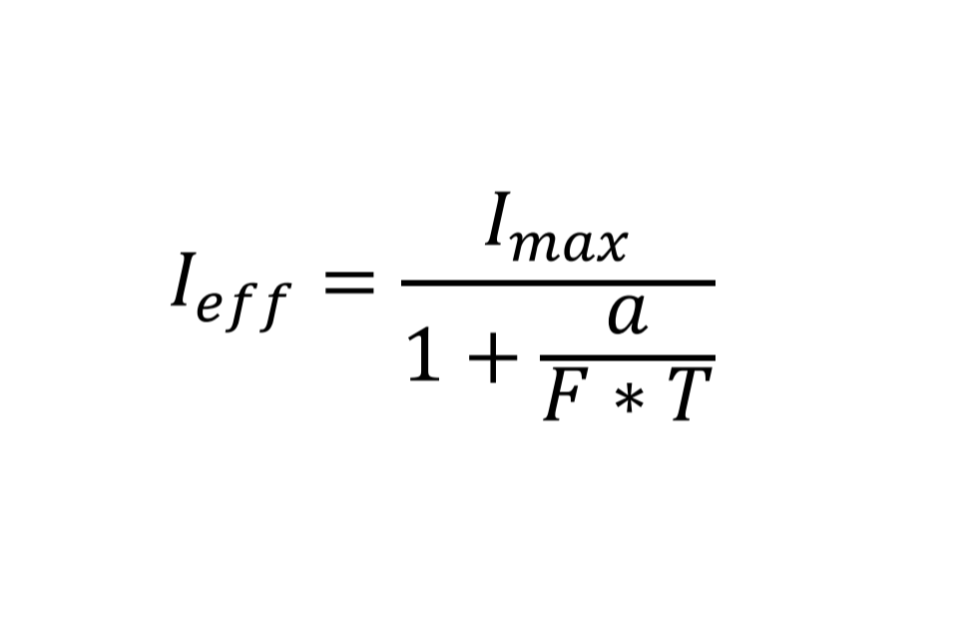
Equation 1
Where F is the form factor given by Equation 2:

Equation 2
and Imax is the maximum instantaneous intensity I(t) and a = 0.2 seconds is the Blondel-Rey constant
7.16 Traffic light camera: response time to signal changes
Where it cannot be proved that the response time is not relevant, the response time of the system to changes in traffic light states must be measured. In particular the following response times must be measured: from red plus amber to green, red without amber to green, red plus amber to blank, and red without amber to blank. A response time of 30 milliseconds or less is expected.
7.17 Time
Any clock not used for critical speed measuring functions but used to record the time of an offence shall be accurate to within one minute over a period of at least seven days at any temperature within the specified range.
7.18 Red X lantern flash rate
The red X device shall not enforce when the flash rate of the lanterns on the red X display is outside the limits set in TSRGD.
8. RF susceptibility test requirement
8.1 Test philosophy
This requirement places emphasis on the ‘WHAT’ and the ‘WHY’ of susceptibility testing, whilst leaving the ‘HOW’ to the vendor.
This means that the Home Office no longer prescribes how a product should be exercised and assessed during testing, but instead expects the vendor – as the ‘expert’ on its own product – to propose a test plan.
The test plan shall not only meet the test requirement but shall also satisfy the Home Office that the vendor properly understands the risks and, where necessary, the mitigation measures to be employed.
Under no circumstances will the test requirement exempt manufacturers or their agents from their obligation to comply with prevailing UK legislation, particularly regulations relating to electromagnetic compatibility and product safety.
8.2 Test plan
Before proceeding with any testing, the vendor must apply for entry to the type approval process (see section 11.2). In stage two of this process the vendor submits test plans for approval by the Home Office. The test plans will be assigned to a Project Officer, who will assess the test plan and notify the vendor in writing as to whether the test plan has been approved or rejected.
If rejected or incomplete, the Project Officer will state the reason and allow the vendor to correct the test plan or to provide more information.
Once approved, the vendor will receive a written confirmation that the test plan meets the test requirements and that it may proceed with formal testing.
To perform a proper assessment of the product and its test plan, the Project Officer needs to have a clear understanding of how the various components connect and interact with one another. This requires a simple yet clear explanation, accompanied by annotated diagrams and comprehensive technical and operational documentation for the entirety of the product. Where any type of stimulator or simulator is used as part of the test method, its principle of operation needs to be illustrated and explained in detail.
Assessment will place particular focus on the evaluation and recommendation of:
- The directions required for appropriate RF exposure;
- The dwell time required to suitably exercise the product;
- The exercise method required to suitably simulate operational functionality;
- The equipment and cable layout during testing;
- Any special conditions requiring additional or enhanced testing.
It is, however, up to the vendor to explain, backed by technical evidence, how the product will be exercised and why the selected exercise method and equipment layout is considered to be fully representative of a typical operational setting.
Equipment not capable of operating accurately and safely within the required levels must incorporate a mechanism to prevent the equipment from operating or to alert the operator to this fact. This mechanism shall be described in detail and the evidence to substantiate it shall be presented and agreed as part of the test plan.
Where a vendor believes that its equipment is likely to malfunction or incur damage as a result of enhanced field strength levels, satisfactory technical justification and evidence need to be produced for consideration by the Project Officer.
In addition to providing any existing EMC test reports and certifications, it will also be helpful if the vendor could make reference to other national and international markets where the product is currently being used.
Where equipment has already undergone EMC testing, the Project Officer will need to see the test plan, the test results and the accreditation of the test laboratory where testing was done. Upon assessing these documents, the Project Officer will decide what further testing needs to be performed.
Ultimately vendors are encouraged to develop and propose new, innovative and cost-effective ways of meeting the new EMC Type Approval requirements.
8.3 Test parameters
For ease of understanding, the new requirement is divided into three parts, a summary of which can be found in ANNEX 1 of this document.
8.3.1 Part 1 – Conducted susceptibility testing as part of CE-marking
This is taken from the CE-marking EMC test requirements and should therefore be performed in accordance with EN61000-4-6.
It covers conducted susceptibility induced by RF via cabling and it applies to all electrical and electronic equipment that have significant lengths of cabling attached during operational use. This usually applies to mobile or stationary equipment, irrespective of power source.
Level 3 of 10 Vrms is applied over a frequency range of 150 kHz to 80 MHz stepping through at 1% frequency increments using 80% AM (amplitude modulation) at 1 kHz.
8.3.2 Part 2 – Radiated susceptibility testing as part of CE-marking
This is taken from the CE-marking EMC test requirements and should therefore be performed in accordance with EN61000-4-3.
It covers radiated susceptibility and applies to all electrical and electronic equipment, whether handheld, mobile or stationary, and irrespective of cabling or power source.
A Class 4 level of 30 V/m (peak of 54 V/m when modulated) is applied over a frequency range of 80 MHz to 6 GHz stepping through at 1% frequency increments using modulation of 80% AM at 1 kHz.
This differs only slightly from most implementations of CE-mark EMC testing in that:
- It covers the full frequency range up to 6 GHz, as opposed to the commonly-used ranges up to 2 GHz and 3 GHz;
- It uses the higher Class 4 (30 V/m) level of RF field strength, as opposed to the commonly-used commercial and industrial levels of Class 2 (3 V/m) and Class 3 (10 V/m) respectively. Class 4 is defined as being appropriate for an environment where portable transceivers are used within 1 m proximity;
- It necessitates thorough and overall RF exposure, meaning that in an attempt to ensure consistent field strength throughout the EUT (equipment under test), irradiation could be required from all six orthogonal directions. As this will increase the duration and cost of testing, other alternatives (for example the use of reverberation chambers as defined in standard EN61000-4-21) may be considered, provided that these alternatives are reliable, repeatable and generally recognised within the EMC community. In any event, alternative methods should be agreed with the Project Officer during the test plan phase.
8.3.3 Part 3 – Additional radiated susceptibility testing
The tests in Part 3 are in addition to those described in Parts 1 and 2, and unless otherwise stated, should also be performed in accordance with EN61000-4-3.
These tests cover radiated susceptibility and apply to all electrical and electronic equipment, whether handheld, mobile or stationary, and irrespective of cabling or power source.
The primary aim of Part 3 is to provide a higher degree of certainty by taking into account two factors that are likely to affect RF susceptibility:
- Increased RF field strength: Increased field strength levels can be the result of a number of things, amongst these being the presence of several RF transmitters operating simultaneously and in close proximity, or the use of RF transmitters near RF-reflecting surfaces.
- Pulse-based amplitude modulation and access method: These types of modulations and access methods have been seen to expose susceptibility weaknesses not observed during use of the standard AM modulation prescribed in Part 2, which amongst others also covers technologies like UMTS and LTE. This could be attributed to the transient nature of the amplitude changes that occur in communication technologies like TETRA, GSM, DCS, Bluetooth, Zigbee and WiFi.
The special conditions in which the above-mentioned factors come into play, along with the enhanced test parameters required to expose them, are described in ANNEX 2 and ANNEX 3.
Part 3 also wishes to draw attention to the possibility of interference between radar TLEDs (traffic law enforcement devices) and vehicle-fitted SRR (short range radar) anti-collision systems, both operating within the 24 GHz band. ANNEX 4 describes the testing that may be required for this type of equipment.
Not all tests in Part 3 necessarily apply to all products; however, tests deemed not applicable need to be agreed with the Project Officer during the test plan phase.
9. Measuring methods
9.1 General
This section describes suitable methods of measurement for carrying out the tests described in previous sections. It is recommended that the methods are followed to ensure uniformity and repeatability of testing. All measuring procedures shall be recorded in the test report. Where speed simulators are used to verify correct performance in immunity testing, it is normally expected that the measured speed will be within ±1 mph of the speed set on the simulator.
9.2 Functional tests
Functional tests shall be undertaken for each location and orientation specified (or at the extremes of any continuous ranges) and for extreme positions of target vehicles. If both monitoring directions are to be used, then all tests shall be repeated for each direction. The components of the device shall be installed according to the manufacturer’s standard installation instructions.
9.3 Offence simulation
The purpose of an offence simulation is to check that the equipment will operate correctly and that the accuracy of the recorded information is maintained under each test condition. During tests, location information should be generated from an appropriate simulator and the camera record an image of a Rugby clock receiver. For equipment controlled by vehicle detectors, except for electromagnetic compatibility tests, appropriate simulators for the vehicle detectors may be used to trigger a simulated offence recording.
Where relevant, both an offence started and stopped by a vehicle detection and an offence started by a vehicle detection and stopped after a fixed time duration shall be simulated
9.4 Speed measurement
A road or track test shall be performed by driving a car fitted with a reference speedmeter calibrated to within 1 mph (1% above 100 mph) past the speedmeter under test at various speeds between 20 mph and the manufacturer’s stated maximum, or 140 mph if less. Tests of the device shall cover all possible configurations by using the maximum number of lanes, at least the extremes of all installation geometries, and the most unfavourable setups. At least 500 measurements shall be taken for each measurement mode, equipment configuration and each vehicle direction. A range of traffic types and traffic and environmental conditions that could conceivably affect measurement accuracy shall as far as possible be reproduced.
9.5 Second method of speed measurement
9.5.1 Photographic and digital cameras
9.5.1.1 If two photographs taken of the same vehicle, with a known time interval, are used to confirm the measurement, the timing accuracy of the camera shutter shall be checked.
9.5.1.2 The following measuring method may be used. A light source should be placed in front of the lens, and a light sensor (for example a biased photodiode) placed inside the camera body at the film plane. When the system is operated, a pulse is generated by the sensor each time the shutter opens. This signal can be connected to a suitable counter/timer set to measure the time difference between the two shutter events (Figure 7).
9.5.1.3 Video cameras
The measuring method used may be to video record the display of a suitable continuously running counter/timer to measure the time difference between 13 frames. If frame counts are used to measure the interval, then a further test shall be carried out to show that the system displays an error message whenever the frame interval does not remain within 1% of 40 milliseconds. This may be demonstrated by synchronising the camera to a signal from an external signal generator and varying its frequency to determine the limits at which an error signal is displayed.
9.5.1.4 Manual distance/time speedmeters
If a video recording system is attached it shall be used to check the secondary speed at five points, approximately equally spaced, during each primary average speed measurement. Otherwise a video camera and recorder shall be temporarily installed in the car to record the secondary speed measurement displayed on the speedmeter.
9.6 Manual distance/time speedmeters
9.6.1 Inherent precision
9.6.1.1 Test setup
For these tests the speedmeter may be tested not installed in a vehicle. The tests may be done using a setup similar to that shown in Figure 6. If the speedmeter includes a video recording system it shall be used to record the results of the tests. Otherwise a separate video camera shall be used to monitor and record the displayed information.
With the speedmeter set to undertake a moving speed check, the test requires the automatic operation of the combined switch to start and stop the check after specified delays with respect to the falling edge of their preceding odometer pulses. Delays of 7/16 and 15/16 of the odometer pulse period are required for the start (i.e. delay (a) in Figure 6) and delays of 1/16 and 9/16 are required for the stop of the check (delay (b)). A delay (delay (c)) is also required so that the time between the start and stop of the check is just sufficient to ensure that the simulated minimum baseline length is just exceeded.
Simulated odometer pulses are applied to the speedmeter during the test and derived from a pulse generator operating at sixteen times the required odometer pulse frequency. The frequency of the pulse generator shall be monitored with a calibrated frequency counter.
9.6.1.2 First tests – minimum speed, distance calibration factor and baseline
Three moving check measurements of the average speed of the speedmeter’s own vehicle shall be simulated as described below using the minimum speed, distance calibration factor and baseline.
The speedmeter shall first be set with a distance calibration factor equal to either 1760 or the manufacturer’s specified minimum by operating the calibration check and applying this number of simulated odometer pulses.
The speedmeter shall then be set to operate a moving check. Simulated odometer pulses shall be applied on the odometer input at a fixed frequency, f Hz, to simulate the speedmeter installed in a vehicle travelling at a constant 20 mph. The frequency f as a function of speed is given by Equation 3 below
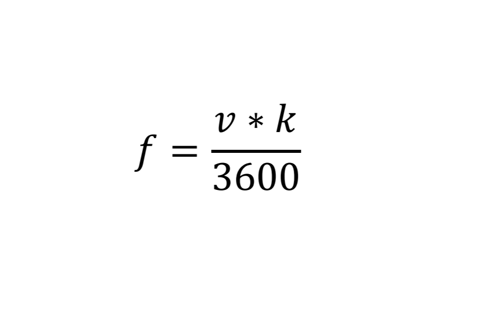
Equation 3
where: f is the simulated odometer pulse frequency in Hz;
v is the simulated constant speed in mph;
k is the distance calibration factor in pulses per mile.
For example for a minimum distance calibration factor of 1760, the simulated odometer pulse frequency for a simulated speed of 20 mph is 9.77778 Hz.
For the first measurement, the combined switch shall be manually operated to start a measurement and operated again to stop the measurement when the elapsed distance exceeds 0.125 miles. The primary average speed displayed on the speedmeter at the end of this check shall be recorded as reading number 1. The displayed information shall also be checked to ensure it shows that the measurement relates to the speed of the vehicle on which the speedmeter would have been installed.
To simulate a moving check started and stopped by the operation of the combined switch operated over a distance that just exceeding the minimum baseline length of 0.125 miles, a delay (delay c) set equal to the nearest number of pulses that exceed one eighth of the set minimum distance calibration factor i.e. k/8 + 1 pulses, is applied as shown in Figure 6. The setup shall enable delay a and delay c to be started simultaneously by activation of switch A. Delay a shall have a pre- selected delay of 7 or 15 pulses from the pulse generator before it activates the combined switch when connected via switch B. Delay b will be triggered from the pulse delayed by delay c before it activates the combined switch when connected via switch B. Delay b shall have a pre-selected delay of 1 or 9 pulses from the pulse generator before it activates the combined switch.
Switch B, the switch between the outputs of delay a and delay b and the combined switch, may be operated manually within 20 seconds of the measurement having commenced.
With this setup the first tests shall be operated twice with the delay settings from Table 1. The primary average speed reading shall be recorded for setting 1 as reading number 2 and for setting 2 as reading number 3.
Table 1 Delays for readings 2 and 3 (see Figure 6):
| Setting | Delay a | Delay b | Reading No. |
|---|---|---|---|
| 1 | 15 | 1 | 2 |
| 2 | 7 | 9 | 3 |
9.6.1.3 Second tests – maximum speed, distance calibration factor and baseline
Three moving check measurements of the average speed of the speedmeter’s own vehicle shall be simulated as described below using the maximum speed specified by the manufacturer, the required maximum distance calibration factor and baseline.
The calibration check shall be used to set the distance calibration factor in the speedmeter under test to the required maximum of 65536. The simulated odometer pulse frequency shall be adjusted to simulate the vehicle in which the speedmeter is installed travelling at the maximum average speed specified by the manufacturer for the speedmeter to measure. The required frequency is given by Equation 3.
The above simulated moving check shall then be repeated with delay c set to 600 seconds and delays a and b set to setting 1 from Table 1. It shall then be repeated again with delays a and b set to setting 2 from Table 1. The primary average speed reading for setting 1 shall be recorded as reading number 4 and for setting 2 as reading number 5.

Figure 6: Inherent error test setup for manual distance/time devices. The pulse generator is set to 16 times the frequency indicated by Equation 3. This is divided by 16 to feed the odometer input of the speedmeter. When Switch A is operated, the combined switch of the speedmeter is operated after a delay of a pulses at a frequency of 16 f, and again after a delay of b + c pulses at this frequency.
9.7 Speed simulators
9.7.1 Doppler radar speedmeters
Simulated speed in the laboratory shall be carried out by generating the Doppler signal at the operating frequency. This may be achieved for non-directional hand- held radars by using a simple modulator consisting of a loudspeaker cone covered with metallic foil and excited with an appropriate frequency, Fd. The cone should be placed a few inches in front of the device under test (Figure 8). Directional radars require either a single sideband modulator (Figure 9) or equivalent mechanical device (Figure 10). The appropriate test frequency, Fd, can be calculated from Equation 4:
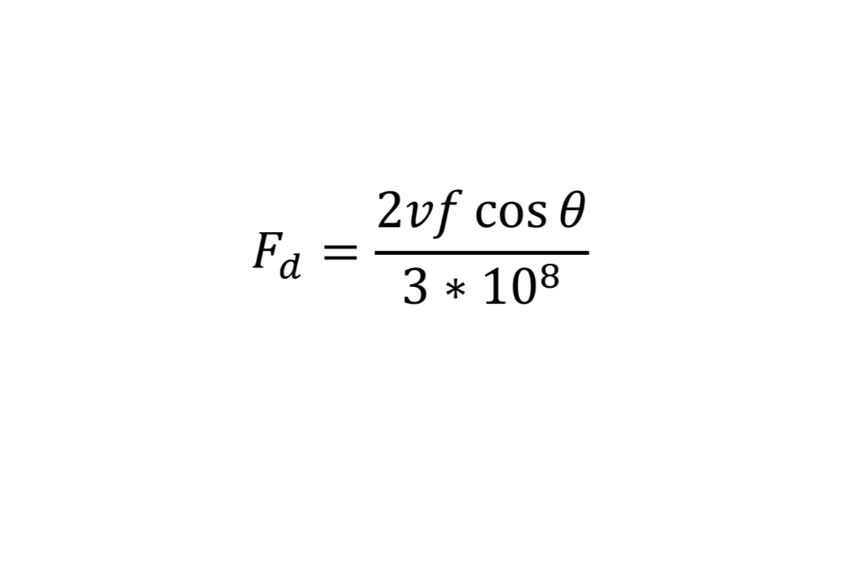
Equation 4
Where: Fd= frequency of the Doppler signal (Hz);
f = measured frequency of transmitted signal (Hz);
v = speed of vehicle (m/s);
𝜃 = angle of beam to direction of movement.
9.7.2 Pressure sensor speedmeters
Pressure sensor devices require a special speed simulator: for electrical cable sensors, a suitable signal simulator capable of generating repetitive pulses equivalent to about 30 mph shall be connected in parallel with the sensor cables at the point where they enter the impedance transformer; speedmeters employing air tubes shall be replaced by an appropriate air-driven speed simulator.
9.7.3 Optical speedmeters
For hand-held devices, the range measurement of a target may be used instead of a speed simulator. Manufacturers shall supply an appropriate simulator for across-the-road devices.
9.7.4 Inductive loop sensor speedmeters
For systems employing inductive loops, laboratory tests may be carried out using substitute inductance instead of full-size loops.
9.7.5 Automatic distance/time speedmeters using image detectors
The speed measurement may be simulated using a fixed image mounted on a bench to trigger both image detectors used to start and stop the measurement and a mechanical shutter to simulate a time of transit over an assumed baseline distance. An independent timer display in the field of view of the image detectors can be used to measure the simulated transit time. Its display shall be of sufficient size to enable a timing resolution of one millisecond to be used to verify the measurement accuracy of the speedmeter. Any fixed baseline greater than or equal to the minimum baseline may be used.
9.7.6 Tracking radar speedmeters
The test house shall use a speed and range simulator designed for this purpose. The test house must provide full details about the device to the Home Office.
9.7.7 Manual distance/time speedmeters
After a distance calibration check using simulated odometer pulses has been done to set a calibration factor at 3520, a constant speed may be simulated for laboratory tests by setting the speedmeter to do a moving check and applying simulated odometer pulses at the rate given by Equation 3. The displayed secondary speed measurement shall display the simulated speed and a primary average speed reading shall be simulated by operation of the combined switch with a time separation sufficient to ensure the simulated distance is greater than 0.125 mile.

Figure 7: Camera shutter timing measurement

Figure 8: Speed simulator for hand-held radar

Figure 9: Speed simulator for directional radar using SSB modulator

Figure 10: Possible arrangement of a mechanical Doppler simulator
9.8 Prohibited lane functional tests
9.8.1 The red X device shall be assessed by the passage of a minimum of 500 vehicles through a lane with and without a red X indication.
9.8.2 Two hundred and fifty or more passages must be undertaken while a red X is displayed, and 250 or more passages must be undertaken while the red X is not displayed.
9.8.3 Each of 50 passages must take place within 60 seconds of the red X being illuminated.
9.8.4 Each of 50 passages must take place within 15 seconds of the red X being extinguished.
9.9 Traffic light cameras: Pulsed LED signal interface
9.9.1 During all tests, except the camera timing test described in section 7.10.1, the LED signal interface shall be connected as specified by the red light camera manufacturer between the traffic light camera and the LED signal head. The LED signal shall be set at its lowest brightness level and positioned within the view of the camera. However it may be positioned outside the measurement area. A photodiode in the camera as shown in Figure 7 may be used as a signal to determine that at least one complete pulse of the LED array is detected in the camera.
9.9.2 In addition in ambient conditions, this arrangement will be used to determine that the camera sees at least one complete pulse of the LED array when the LED signal is set to every brightness setting of the LED signal head.
9.10 Environmental tests
9.10.1 At each temperature step in the working temperature range, the equipment shall be checked by performing an internal calibration check and a simulated offence. If a speedmeter is operated with a variable speed limit sign, for the simulated speed measurement it shall be connected to a sign, or a simulator of the sign, with a correct speed limit displayed. After a speed measurement exceeding the enforcement threshold is simulated, further simulations of the same speed measurement shall be made after the displayed speed limit is lowered until enforcement is again enabled. No enforcement shall occur for at least one minute after the displayed speed limit is changed.
9.10.2 Care shall be taken to ensure that any fans, thermostats, or other electronic control devices associated with the environmental chamber do not cause spurious readings during the testing cycle.
9.11 Variable message signs
9.11.1 When using a variable message sign with in-built aspect verification or a simulator of the sign connected to the detection device, the following fault conditions shall be simulated while a red X or a speed measurement of 90 mph is simulated:
- Failure of any light source used to illuminate any individual pixel of the speed limit ore red X aspect;
- Power-up of any individual pixel that should not be illuminated.
No enforcement or enforcement only of the National Speed Limit shall occur while these fault conditions are simulated.
9.11.2 When using a variable message sign connected to the device and external aspect verification, the following fault condition shall be simulated while a red X or speed measurement of 90 mph is simulated:
- i. Failure of a pattern of bulbs outside the limits set by National Highways (templates of unacceptable displays may be provided by National Highways for this purpose).
No enforcement or enforcement only of the National Speed Limit shall occur while this fault condition is simulated.
9.12 Stop/start and door alarm frames
For automatic equipment which records on analogue video tape and is to be used in unattended operations, recordings shall be made to test that the requirements in 5.9.4 and 7.3 have been met. A sequence of at least 10 recordings automatically started by simulating a stream of vehicles detected at the start of the recording zone above the enforcement threshold shall be made. Vehicle gaps above and below 10 seconds shall be simulated. A further recording shall be made by manually commencing recording without the detection of any vehicles being simulated. During the recording, the door shall be opened to generate a door alarm frame and then closed again to allow the recording to continue. The recording may then be stopped manually or by filling the recording capacity. The recordings shall be examined to determine whether the requirements have been met.
9.13 Vehicle detection
For equipment automatically controlled by vehicle detectors, the information content of the resultant images shall be investigated by simulating at least five offences. This shall also show the quality of the resultant images.
9.13.1 Speed threshold
The accuracy of the speed measurement used by the vehicle detector shall be tested for speed thresholds set at various speeds between 30 mph and 90 mph. At each threshold setting, the lowest speed at which the video recording is triggered shall be measured by simulating different speeds in increments of 1 mph.
10. Calibration
10.1 General requirements for all devices
10.1.1 The complete calibration process should be carried out annually. Any maintenance work on a device shall be followed by functional checks to determine whether the calibration of the device remains valid. If not, the complete calibration procedure shall be undertaken.
10.1.2 Adequate test equipment and facilities shall be available to the person carrying out the calibration procedure. All equipment used for calibration shall be certified annually by a competent body with equipment traceable to national standards.
10.1.3 Prior to calibration of the enforcement device, the calibration records of the test equipment to be used shall be checked to ensure they have been tested within the last year with equipment traceable to national standards.
10.1.4 A calibration certificate shall be supplied to the police force using the device, with a copy held on record by the person who has calibrated the device. In addition to device specific requirements listed later in this document, the calibration certificate shall include:
- The name and company of the individual who undertook the calibration;
- The device manufacturer, type/model and serial number;
- The date on which the calibration was conducted;
- A certificate number and the date issued;
- A statement to the effect that any parts or components replaced are identical to those used in the device as type-approved;
- The signature of the person who undertook the calibration.
10.1.5 Any continuation sheets shall also be clearly marked with the certificate number, date, and device serial number.
10.1.6 The calibrator shall keep on record with a copy of the certificate, a log of all calibration measurements obtained and any observations made, marked with the same certificate number, date and device serial number. This log shall be made available for inspection by the Home Office.
10.1.7 The calibrated equipment should be marked with an adhesive label stating; the date of calibration, the date on which the next calibration is required, along with the signature of the person who carried out the calibration.
10.2 Additional requirements for automatic equipment
10.2.1 Tests
10.2.1.1 All in-built test routines shall be run and the results recorded.
10.2.1.2 If there is a flash unit or other means of illumination this shall be visually inspected. The flash button and actual operation of the flash shall be checked.
10.2.1.3 The timing of the secondary check shall be measured. This may be achieved, for example, by using a free running millisecond counter confirming that the time difference displayed in the secondary check evidence is within the tolerance set by the manufacturer. At least 3 measurements shall be taken at both the minimum and maximum possible delay times. These shall be recorded.
10.2.1.4 All bulbs, buttons, switches, plugs, and connectors on any recording equipment are to be checked for proper operation.
10.2.2 Documentation
10.2.2.1 If, and only if, the device passes all of the tests specified in 10.2.1 then a calibration certificate shall be produced in accordance with 10.1.4.
10.2.2.2 In addition a statement verifying that the timing of the secondary check is within the manufacturer’s tolerance shall appear on the calibration certificate.
10.3 Additional requirements for radars
10.3.1 Tests
10.3.1.1 All in-built test routines shall be implemented, and the results recorded.
10.3.1.2 The operating frequency of the radar shall be measured and recorded. It shall be within the operating range specified by the manufacturer.
10.3.1.3 A minimum of five speeds shall be simulated covering a speed range of at least 20 mph to 80 mph. All simulated and measured speeds observed shall be recorded. To pass, all shall agree to within ± 1 mph.
10.3.1.4 If a tuning fork is used for checking the correct operation of the radar, then its frequency shall be measured and recorded. The speed produced on the radar using the tuning fork shall be measured and shall be within ± 1 mph of its specified simulation speed.
10.3.2 Documentation
10.3.2.1 If, and only if, the radar passes all of the tests specified in 10.3.1, a calibration certificate shall be produced in accordance with 10.1.4, and 10.2.2 if applicable.
10.3.2.2 In addition the following information shall appear on the calibration certificate:
- The specified and measured operating frequency of the radar;
- The serial number of the tuning fork, if used;
- The specified and measured frequency of the tuning fork;
- A table of simulated speeds and corresponding measured speeds.
10.4 Additional requirements for hand-held optical devices
This section refers to optical devices which calculate speed from a series of range measurements.
10.4.1 Tests
10.4.1.1 All in-built test routines shall be run, and the results recorded.
10.4.1.2 The pulse repetition frequency shall be measured either externally to the device, or by internal measurement of the appropriate quartz clock. It shall be within the operating range specified by the manufacturer.
10.4.1.3 The horizontal and vertical alignment of the laser beam with the sight shall be checked using the method recommended in the device user manual.
10.4.1.4 If a simulator is available, a minimum of five speeds shall be simulated covering a speed range of at least 20 mph to 80 mph. All simulated and measured speeds observed shall be recorded. To pass, all shall agree to within ± 1 mph. Alternatively, the device shall be checked functionally against another type- approved speed measuring device which can be calibrated by simulation. At least 5 speeds shall be measured and compared, covering a speed range of at least 20 mph to 80 mph. To pass, these should agree to within the combined tolerances stated by the manufacturers.
10.4.1.5 The device shall be used to make at least 3 different range measurements against 3 accurately measured distances of between 25 and 100 metres to a reflective target. These distances, as well as the speed readings if present (which should always be 0 mph when measuring a fixed target) shall be recorded throughout this test. To pass, they shall all be within the manufacturer’s stated tolerance.
10.4.2 Documentation
10.4.2.1 If, and only if, the device passes all of the tests specified in 10.4.1, a calibration certificate shall be produced in accordance with 10.1.4, and 10.2.2 if applicable.
10.4.2.2 In addition the following information shall appear on the calibration certificate:
- The pulse repetition frequency or appropriate clock frequency shall be listed against the expected value;
- A statement verifying that the alignment is correct;
- A table of simulated speeds or speeds measured from another type- approved device, and corresponding measured speeds;
- A table of actual and corresponding measured range. If presented, the corresponding speed readings shall also be listed, or a statement given verifying they were all 0 mph.
10.5 Additional requirements for pressure sensor and across-the-road optical devices
10.5.1 Tests
10.5.1.1 All in-built test routines shall be run and the results recorded.
10.5.1.2 A minimum of five speeds shall be simulated covering a speed range of at least 20 mph to 80 mph. All simulated and measured speeds observed shall be recorded. To pass, all shall agree to within ± 1 mph.
10.5.2 Documentation
10.5.2.1 If, and only if, the device passes all of the tests specified in 10.5.1 then a calibration certificate shall be produced in accordance with 10.1.4, and 10.2.2 if applicable.
10.5.2.2 In addition, a table of simulated and corresponding measured speeds shall appear on the calibration certificate.
10.6 Additional requirements for traffic light cameras
10.6.1 Tests
10.6.1.1 All in-built test routines shall be run and the results recorded.
10.6.1.2 The flash unit shall be visually inspected. The flash button and actual operation of the flash shall be checked.
10.6.1.3 The operation of the loop detector shall be monitored by passing a metal object over a simulated loop set-up. This operation shall also be checked with the flash firing with the traffic light on red. These results shall be recorded.
10.6.1.4 Camera timing shall be measured. This may be achieved by using a free running millisecond counter confirming that the time difference displayed in the two pictures is within the tolerance set by the manufacturer. At least 3 measurements shall be taken at both the minimum and maximum possible delay times. These shall be recorded.
10.6.1.5 All bulbs, buttons, switches, plugs, and connectors are to be checked for proper operation.
10.6.1.6 If the device outputs a speed value, a series of speed measurement tests shall be carried out using a speed simulator at the loop spacing typically used for the device operationally. A minimum of five speeds shall be simulated covering a speed range of at least 20 mph to 80 mph. To pass, all shall agree to within ± 1 mph.
10.6.1.7 Any LED displays shall be checked for correct operation.
10.6.1.8 When a correct signal sequence is applied, activation of the loop detector shall be simulated at 1.0, 1.6, and 2.0 seconds after the red signal with an activation threshold set at 1.5 seconds. For each condition a record shall be made of whether the system was activated, and when activated, what the indicated time into red was. To pass, no activation shall occur in the 1.0 second test, and the indicated times into red shall be within the tolerance set by the manufacturer.
10.6.2 Documentation
10.6.2.1 If, and only if, the device passes all of the tests specified in 10.6.1 then a calibration certificate shall be produced in accordance with 10.1.4.
10.6.2.2 In addition the following information shall appear on the calibration certificate:
- A table of simulated speeds and corresponding measured speeds;
- A table of simulated time into red and corresponding indicated time into red, and a statement verifying the system only activated above the set threshold.
11. Type-approval procedures
11.1 Manufacturers or their appointed agents seeking type-approval should contact the Home Office Police Powers Unit (PPU) at:
Police Powers Unit Home Office
6th Floor Fry Building
2 Marsham Street
London
SW1P 4DF
Or email: HOTA-Submissions@homeoffice.gov.uk
11.2 On request PPU will provide a copy of the latest version of the ‘Home Office Type Approval of Collision Reduction Equipment Submission Form’ and associated guidance notes. The guidance notes outline the process and evidence requirements to apply for Home Office Type Approval. Briefly, if accepted into the process, manufacturers or their approved agents will be required to provide further information as directed by the submission form, including plans for testing the device. If and once test plans are approved, independent test laboratories with ISO 17205 accreditation and acceptable to the Home Office should be commissioned to carry out and report on the tests.[footnote 12] Manufacturers or their agents are expected to bear the full costs of the private test laboratory’s evaluation work. On completion of their work, the private test laboratory will submit a report on their evaluation of the device to the Home Office. It is the responsibility of the manufacturer or agent to demonstrate full and complete compliance with the principles outlined in this handbook.
11.3 To back up type-approval, the Home Office prepares a supporting agreement for signature by the manufacturer and by Home Office officials which is primarily directed at preventing the manufacturer from altering the device in question in any way without the prior approval of the Secretary of State. Manufacturers must agree:
- Not to change the device without the agreement of the Secretary of State;
- To ensure that the type and serial number of each device is clearly identified by an indelible marking;
- To ensure that the serial number is unique to each device and that each device is numbered consecutively;
- To ensure that any repair or calibration facility relating to the device is open to inspection;
- To supply free of charge to the Secretary of State full information about the device, including, not exclusively, a full circuit diagram of the device with all the circuit components clearly indicated, complete bespoke and critical software listings, a full and detailed technical description, and transparent software and firmware verification procedures;
- If required, to supply a device free of charge to the Secretary of State and that the Secretary of State shall not be responsible for any damage caused to the device while it is in his possession.
This agreement must be signed by the manufacturer or agent prior to the Home Secretary signing the formal type-approval document.
Annex 1: Summary of RF susceptibility test parameters
Part 1: Conducted susceptibility testing as part of CE-marking
| Frequency band | 150 kHz to 80 MHz |
| Level | 10 Vrms |
| Modulation | 80% AM at 1 kHz |
| Steps | 1% frequency increments |
| Dwell time | To be agreed in test plan |
| RF exposure | Cable-induced |
| Exercise method | To be agreed in test plan |
Part 2: Radiated susceptibility testing as part of CE-marking
| Frequency band | 80 MHz to 6 GHz |
| Field strength | 30 V/m (peak of 54 V/m when modulated) |
| Modulation | 80% AM at 1 kHz |
| Steps | 1% frequency increments |
| Dwell time | To be agreed in test plan |
| Antenna polarisation | Horizontal and vertical |
| Horizontally-rotated exposure | To be agreed in test plan |
| Vertically-rotated exposure | To be agreed in test plan |
| Exercise method | To be agreed in test plan |
Part 3: Additional radiated susceptibility testing
a. TETRA
| Frequency band | 380 MHz to 424 MHz |
| Field strength | 65 V/m peak (see Annex 2 for exceptions) |
| Modulation | Pulse-based AM (see Annex 3 for setup) |
| Steps | 1% frequency increments |
| Dwell time | To be agreed in test plan |
| Antenna polarisation | Horizontal and vertical |
| Horizontally-rotated exposure | To be agreed in test plan |
| Vertically-rotated exposure | To be agreed in test plan |
| Exercise method | To be agreed in test plan |
b. GSM, DCS, Bluetooth, Zigbee, WiFi
| Frequency band | 868 MHz to 2.5 GHz and 5 to 6 GHz |
| Field strength | 54 V/m peak |
| Modulation | Pulse-based AM (see Annex 3 for setup) |
| Steps | 1% frequency increments |
| Dwell time | To be agreed in test plan |
| Antenna polarisation | Horizontal and vertical |
| Horizontally-rotated exposure | To be agreed in test plan |
| Vertically-rotated exposure | To be agreed in test plan |
| Exercise method | To be agreed in test plan |
c. Short range radar
| Frequency band | 24.15 GHz |
| Field strength | 0.2 V/m peak (see Annex 4 for guidance) |
| Modulation | CW (unmodulated carrier wave) |
| Dwell time | To be agreed in test plan |
| Antenna polarisation | To be agreed in test plan |
| RF exposure | Into TLED antenna |
| Exercise method | To be agreed in test plan |
Annex 2: Field strength requirements for TETRA in vehicles
Although Annex 1 Part 3a sets a susceptibility test level of 65 V/m for equipment that will not be operated within 20 cm of a TETRA transceiver, there are environments where this level does not adequately cover the levels measured during testing.
The interior of a typical vehicle is one such example, where studies have demonstrated a multiplicative effect on RF fields originating from transmitter antennas located inside the vehicle. This has led to the development of the more- stringent susceptibility requirements described below.
Any equipment operated inside a vehicle in which a TETRA transceiver, along with its antenna, is also present and switched ON, must meet the minimum susceptibility field strength requirements as prescribed in Table 2 below. It is, however, strongly advised that for general in-vehicle use, vendors design and test their equipment to at least the 160 V/m level. As the presence of two TETRA handsets inside a vehicle is the most recurrent operational scenario, a level of 160 V/m is likely to be specifically requested.
Table 2 TETRA field strength requirements within vehicles:
| Circumstance | Applicable test | Field strength |
|---|---|---|
| For equipment to be used inside a vehicle, where the possibility exists that at least three TETRA handsets could be present inside the vehicle | Part 3a | 200V/m peak |
| For equipment to be used inside a vehicle, where no more than two TETRA handsets will be present inside the vehicle | Part 3a | 160V/m peak (recommended) |
| For equipment to be used inside a vehicle, where no more than one TETRA handset will be present inside the vehicle | Part 3a | 125V/m peak |
| For equipment to be used inside a vehicle, where only the vehicle-fitted TETRA radio with an externally- mounted antenna, will be present | Part 3a | 65V/m peak |
| For equipment that will never be used inside a vehicle, nor be used at a proximity of less than 20 cm from any TETRA handset | Part 3a | 65V/m peak |
Annex 3: Bespoke test modulation for pulse-based technologies
Studies have shown pulse-based AM to be more disruptive to nearby electronic equipment than the traditional sine wave-based AM used in EMC susceptibility testing. For this reason, two bespoke modulation schemes are used – pseudo- TETRA and ED130-specified.
Pseudo-TETRA
This test modulation emulates typical TETRA modulation schemes and applies only to testing in the band 380 to 424 MHz. It comprises an 18 kHz square wave, with a pulse repetition frequency (PRF) of 17 Hz using a duty cycle of 50%. The carrier is modulated to a depth of >98%. This is illustrated in Figure 11 below.

Figure 11: Pseudo-TETRA test modulation
ED130-specified
This test modulation emulates typical TDMA-, CSMA- and FHSS-based modulation and access schemes used in technologies like GSM, DCS, Bluetooth, Zigbee and WiFi. It applies only to testing in the bands 868 MHz to 2.5 GHz and 5 to 6 GHz. It comprises an unmodulated square wave, repeated at 200Hz using a duty cycle of 12.5%. The carrier is modulated to a depth of >98%. This is illustrated in Figure 12. Note: CDMA/FDMA-based technologies like UMTS and LTE are covered by the normal AM modulation scheme prescribed in Annex 1 Part 2.

Figure 12: ED130-specified test modulation
Annex 4: Radar traffic law enforcement devices
UK police radar speed TLEDs operate in the band 24.05 to 24.15 GHz, whereas anti-collision radars in vehicles operate in the band 24.15 to 24.25 GHz.
Although radar TLEDs are extremely unlikely to be affected by the low RF levels of these devices via ‘back door’ coupling (coupling not via the TLED’s antenna), the possibility of them being affected via ‘front door’ coupling (via the TLED’s antenna) is greater. As such, it is expected of vendors to ensure that radar equipment is sufficiently resilient against short range devices.
It is recommended that testing be conducted at 24.15 GHz with the TLED antenna being irradiated by an unmodulated carrier wave with a field of 0.2 V/m peak from a distance greater than 1 m.
-
National ANPR Standards for Policing and Law Enforcement 2019 ↩
-
PSDB Publication 3/96 has been superseded, but it may provide useful background: Lewis, S.R. (1996) ‘Outline Requirements And Specification For Automated Traffic Enforcement Systems’ PSDB Publication 3/96 ↩
-
SP 800-38B, Recommendation for Block Cipher Modes of Operation: the CMAC Mode for Authentication - CSRC ↩
-
SP 800-38A, Recommendation for Block Cipher Modes of Operation: Methods and Techniques - CSRC ↩
-
Subject to NIST’s advice on post-quantum cryptography ↩
-
The display of time in seconds is optional. ↩
-
The indication of time to the nearest minute is acceptable. ↩
-
Ohno, Y., Couzin, D., (2002) ‘Modified Allard Method for Effective Intensity of Flashing Lights’, Proceedings of the CIE Symposium ‘02 on Temporal and Spatial Aspects of Light and Colour Perception and Measurements, 22-23 August, 2002, Veszprém (Hungary) ↩
-
The results of checks and tests carried out by the bodies and laboratories of other member states may be taken into consideration where such results provide a level of accuracy, fitness and suitability for purpose equivalent to the results of tests carried out in the United Kingdom, and where such bodies and laboratories offer suitable and satisfactory guarantees of technical and professional competence and independence. ↩