Abdominal aortic aneurysm screening: ultrasound equipment quality assurance guidelines
Updated 22 March 2019

© Crown copyright 2019
This publication is licensed under the terms of the Open Government Licence v3.0 except where otherwise stated. To view this licence, visit nationalarchives.gov.uk/doc/open-government-licence/version/3 or write to the Information Policy Team, The National Archives, Kew, London TW9 4DU, or email: psi@nationalarchives.gov.uk.
Where we have identified any third party copyright information you will need to obtain permission from the copyright holders concerned.
This publication is available at https://www.gov.uk/government/publications/abdominal-aortic-aneurysm-screening-ultrasound-equipment-guidance/abdominal-aortic-aneurysm-screening-ultrasound-equipment-quality-assurance-guidance
1. Background
This publication provides guidance on the quality assurance of ultrasound equipment used in the NHS abdominal aortic aneurysm (AAA) screening programme.
It is recognised that access to formal ultrasound quality assurance (QA) across England is variable but equipment used in national screening programmes must be quality assured.
This guidance sets out evidenced-based methods for the testing and monitoring of ultrasound scanners that can be undertaken by screening staff between annual assessment by medical physics departments or any other qualified provider. It also recognises that, with appropriate training and monitoring, screening technicians can perform monthly QA checks.
2. Screening equipment used in the NHS AAA Screening Programme
The 2 systems that can be bought for use in the programme are:
- MIS Samsung HM70A with Plus
- Mindray M8
Both systems are equipped with harmonic and compounding imaging modes that are normally switched on for screening. These should be disabled for the sensitivity and noise tests outlined in this document.
In addition, two other scanner models are still in use by the national programme from the implementation phase, but most will have reached the end of their lifespan and should have been replaced by the models above.
Future equipment evaluation projects may lead to the introduction of new ultrasound models. The equipment QA policy will apply to all new systems.
3. Scope
QA of ultrasound equipment is of fundamental importance to ensure safety, correct functioning of equipment, and the accuracy and reproducibility of electronic calliper diameter measurements [footnote 1] [footnote 2].
More information is provided by:
-
the Institute of Physics and Engineering in Medicine policy statement on the role of the clinical scientist in medical ultrasound
- the Society and College of Radiographers and British Medical Ultrasound Society guidelines for professional practice
-
guidance published by the British Medical Ultrasound Society.
- the Institute of Physics and Engineering in Medicine policy statement on the role of the clinical scientist in medical ultrasound
- the Royal College of Radiologists guidance on the provision of ultrasound services
- the Society and college of radiographers and British Medical Ultrasound Society guidelines
Historically, regular performance of ultrasound equipment was assessed using tissue equivalent test objects. However, there are a number of limitations to this approach. Tissue equivalent test objects are expensive, can deteriorate with age and staff with expert knowledge are required to perform the testing.
Modern ultrasound scanners use digital electronics to produce ultrasound images and there are no moving parts within the transducer and consequently no calibration adjustments that the operator can perform. However, you can monitor the performance of the equipment using a range of simple routine tests.
If objective testing demonstrates significant deterioration, this can also provide evidence for the replacement of older equipment.
This document is based on recommendations published by the Institute of Physics and Engineering in Medicine [footnote 1], the Institute of Physics and Engineering in Medicine policy statement and the British Medical Ultrasound Society [footnote 2].
The guidance comprises 4 specific elements. They are as follows.
-
Acceptance testing on delivery of new equipment to be performed by the regional medical physics department or any other qualified provider.
-
Safety checks before each scanning session.
-
Monthly performance tests to be carried out by ultrasound quality assurance lead, appropriately trained clinical skills trainer (CST) or appropriately trained screening technicians
-
Annual performance checks conducted by the regional medical physics department in line with local trust policy of monitoring the performance of ultrasound equipment.
Where services are unavailable, the equipment manufacturer as part of a service contract or any other qualified provider can undertake this assessment.
4. Acceptance testing
Acceptance tests must be completed before new ultrasound systems enter service into the local screening programme. These should include the following checks.
-
The scanner will be checked for electrical safety by the medical physics department. and sticker attached to indicate when the next check is due.
-
The equipment must be logged onto an appropriate medical equipment asset register and appropriate stickers attached to the equipment to identify this has been completed.
-
An assessment of the accuracy of electronic measurement callipers, including axial and lateral resolution, should be assessed using either an open topped test object or tissue equivalent test object. The overall penetration of the system should be assessed using an AAA specific preset with harmonic imaging and compound imaging disabled. These tests should be performed by the local medical physics department or, if this is not possible, by the equipment supplier at installation. A record of the values must be retained for future comparison by the screening programme.
-
Image uniformity should be assessed in line with IPEM report 1021 and BMUS guidelines.
-
A baseline sensitivity test should be performed by imaging dry in air as recommended by IPEM Report 102 and BMUS guidelines. Measurement of the depth of reverberation lines is a proxy for sensitivity. Harmonic imaging and compound imaging should be disabled for this test. A depth setting between 6cm and 8cm, dependent on the system, should be adequate to accommodate the reverberation pattern. This measurement is a baseline for subsequent tests. IPEM report 102 recommends that the acceptable range for future tests is ±distance to the next reverberation line.
-
A record of the pre-sets and control settings used during testing and images must be retained for future testing and reference. Reports and documentation will be retained by the local screening programme.
-
It is recommended that all programmes have service contracts in place. Ideally these should provide preventative maintenance visits on an annual basis.
5. Safety checks
Before each screening session the operator will do the following checks:
-
Check that the scanner is clean and there is no contamination from gel or accumulation of dust or other debris on the surfaces or around controls.
-
Check the scanner for any visible damage such as cracks to the casing or damage to control buttons, switches and the keyboard or screen. Pay particular attention to identifying cracking around handles and corners of the display screen.
-
Check the integrity of the mains cable and if present, power transformer. Make sure there are no breaks in the cable outer insulation and, in particular, that there is no kinking or breaks in the cable at the point where it joins the mains plug, transformer or the ultrasound machine. If any damage is identified the machine must be removed from service and the fault reported and rectified.
-
Check the integrity of the transducer cable, connector and transducer head. This includes breaks in the cable or damage, cracks or splits in the latex lens surface of the transducer face (Figure 1). If there is damage to the transducer face this could result in electrical risk with gel or water ingress to the transducer elements. If such damage is identified, the scanner must be taken out of service for further evaluation.
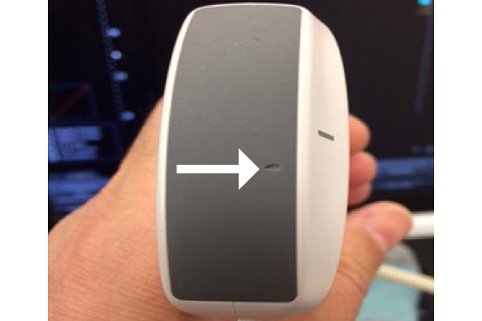
Figure 1. Inspection of the transducer face demonstrates an obvious area of damage shown by the arrow. The probe should be removed from use and assessed by the medical physics department, equipment manufacturer or maintenance provider
-
When the scanner is switched on, look for any error messages or obvious abnormalities such as a flickering screen or excessive noise in the image that might indicate a problem.
-
Ensure the correct imaging pre-set has been selected and that the B-mode grey scale bar at the side of the image display can be fully visualised to display dark grey to black at one end and peak white at the other with a smooth graduation between the 2 ends.
-
Look at the uniformity of the dry in air reverberation pattern to check for irregularity that might indicate element drop out or transducer damage, particularly if this is evident during imaging (Figure 2).
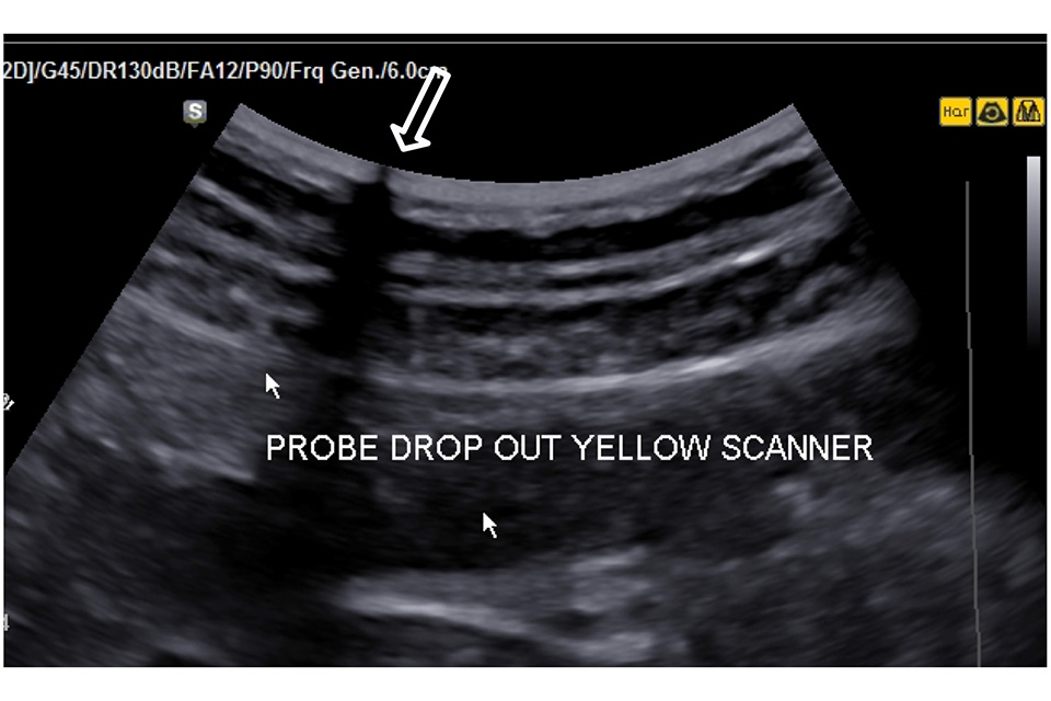
Figure 2. There is a transducer transmission fault at the point shown by the large arrow resulting in a significant loss of image along the transmission line. This probe should be removed from service and repaired or replaced
-
A log of faults, actions and outcomes should be recorded and retained by the local screening programme for each scanning system.
-
At the end of each scanning session make sure that the scanner and cables are completely clean using manufacturer recommended cleaning wipes and agents.
6. Monthly testing
Screening technicians can undertake monthly equipment QA testing but only if this has been agreed by the local programme following training and assessment.
The training and assessment must be conducted by the local programme staff who currently undertake equipment QA. This would normally be the QA lead, CST or medical physicist, or a combination of these staff.
The criteria outlined below must be fulfilled.
The screening technician must not be a trainee. A screening technician must have completed and passed the Health Screener Diploma (HSD). A screening technician who qualified before the HSD can be trained to undertake monthly testing of equipment as set out in this document.
A formal training session of at least half a day must be provided at local level. This should include theory and practical teaching supported by reference material. An ultrasound system must be available in the training session to demonstrate the QA procedure, including machine settings and documentation of measurements.
Screening technicians must pass a formal assessment of practical competence conducted by the QA lead, CST or medical physicist. The screening technician must demonstrate that they can successfully undertake and document all tests listed in the monthly equipment QA schedule.
This must be repeated at least 3 times during the same assessment session. This will allow the screening technician to demonstrate that they can obtain consistent results. The scanner must be switched off, then switched back on and set to a standard AAA pre-set between each testing cycle.
This will allow the screening technician to demonstrate that they can correctly configure the scanner settings for the equipment QA process.
The QA lead, CST or medical physicist is responsible for signing a document of competence, which must be retained by the local programme.
If the screening technician is not able to demonstrate consistent measurements within the 3 cycles, further training and assessment is required.
Following satisfactory assessment and sign-off of competence, the QA lead, CST or medical physicist must:
- observe the screening technician undertaking their first monthly equipment QA session to provide support and feedback
- review the results of subsequent monthly equipment QA tests performed by the screening technician to be aware of any equipment problems
- undertake an observational assessment of the screening technician performing equipment QA at least once every 6 months to provide feedback
- identify any subsequent sub-standard performance and take appropriate action
Local programmes must document whether individual screening technicians have been trained to undertake equipment QA and document the observational assessment by the QA lead, CST or medical physicist. Screening technicians can include the training in their continuing professional development portfolio.
The QA lead, CST or appropriately trained screening technician will inspect the equipment on a monthly basis and retain a log of findings recordings, faults and actions retained.
Monthly testing includes imaging tests to be performed using the same scanner settings as initial acceptance testing. Harmonic, imaging, compound imaging and any other advanced image processing should be disabled and the overall transducer gain set to maximum.
The TCG sliders should be set to the mid position and a single focus point positioned at the most superficial level within the image screen. The viewing and ambient light conditions should be the same for all monthly testing sessions.
The following tests must be undertaken to assess scanner and transducer integrity and, sensitivity and performance:
The scanner and equipment should be checked as recommended before daily use (see checklist above).
Image uniformity should be tested as recommended in by IPEM report 102 and BMUS guidelines. Problems such as axial banding may indicate a transmission or reception fault.
Transmission and element faults can be checked by running a paper clip over the surface of the probe following application of a very thin layer of coupling gel. Look for any loss of echoes as the clip is moved across the transducer face.
This can be more difficult to spot at the sides of the image sector.
Perform a sensitivity test by imaging dry in air as recommended by IPEM report 102 and BMUS guidelines. Images or measurements should be recorded for comparison with previous tests, including the acceptance test.
Perform an electronic noise assessment test as recommended in IPEM report 102 and BMUS guidelines.
Check when the next electrical safety check is due. This is normally shown on tags attached to the scanner or recorded in the equipment log.
The local screening programme must retain reports and documentation for each scanner.
7. Annual testing
Annual assessment of the systems is performed by the medical physics department, by the equipment manufacturer as part of preventative maintenance or by any other qualified provider using an appropriate test object in line with IPEM report 102.
Annual testing includes:
- measurement accuracy of electronic callipers including axial and lateral resolution
- penetration assessment
- assessment of transducer integrity
- general equipment inspection and electrical safety
The local screening programme retains reports and documentation. Local policies may require more frequent inspections.
The performance and sensitivity of ultrasound machines can be monitored by regular testing as outlined in this document. This will also help identify deterioration that will support decision making regarding the need for replacement equipment that can be reported to programme boards.
7.1 Equipment logs
It is important that equipment checking and testing logs are kept up to date and maintained as local programmes may be called upon to provide these as evidence that appropriate checking processes have been undertaken and acted upon, as part of the ongoing quality assurance programme delivered by Public Health England.
The Institute of Physics and Engineering in Medicine (IPEM) report can be obtained directly from the IPEM.