Technical Annex - List of Schedules
Published 8 December 2022

© Crown copyright 2022
This publication is licensed under the terms of the Open Government Licence v3.0 except where otherwise stated. To view this licence, visit nationalarchives.gov.uk/doc/open-government-licence/version/3 or write to the Information Policy Team, The National Archives, Kew, London TW9 4DU, or email: psi@nationalarchives.gov.uk.
Where we have identified any third party copyright information you will need to obtain permission from the copyright holders concerned.
This publication is available at https://www.gov.uk/government/publications/msn-1699m-amendment-3-the-merchant-shipping-passenger-ship-construction-ships-of-classes-iii-to-via-regulations-1998/technical-annex-list-of-schedules
List of Schedules
Schedule 1: Intact Stability Standard
Schedule 2: Survivability and watertight subdivision arrangements
| Section 1: | Standards of survivability |
| Table 1: Standard of survivability for ships built before 31st October 1992 | |
| Table 2: Standard of survivability for ships built on or after 31st October 1992 | |
| Section 2: | Ships required to be subdivided |
| Section 3: | The Heeling test |
| Section 4: | The Buoyancy test |
Schedule 3: Stability in the damaged condition
| Section 1: | Assumptions on which the calculations are to be based |
| Section 2: | Sufficiency of stability in the damaged condition of ships constructed before 29th April 1990 |
| Section 3: | Sufficiency of stability in the damaged condition of ships constructed on or after 29th April 1990 |
Schedule 4: Construction of watertight bulkheads etc.
Schedule 5: Subdivision load lines
Schedule 6: Bilge alarms, Bilge pumps and bilge piping
Schedule 7: Emergency and transitional source of electrical power and emergency switchboard
Schedule 8: Storage and distribution of oil and gaseous fuel
Schedule 9: Steering gears
Schedule 10: Openings in shell plating below the bulkhead deck
In this Merchant Shipping Notice:
-
references to regulations in the Schedules, unless otherwise stated, refer to regulations in the Merchant Shipping (Passenger Ship Construction: Ships of Classes III to VI(A)) Regulations 1998;
-
a reference to a numbered paragraph is, unless otherwise stated, a reference to the paragraph of that number in that Schedule;
-
a reference to a numbered section is, unless otherwise stated, a reference to the section of that number in that Schedule;
-
a reference to a numbered Schedule is, unless otherwise stated, a reference to the Schedule of that number in this Merchant Shipping Notice.
In this Notice the following expressions have the following meanings respectively, except where the context requires otherwise:
“approved” means approved by the Secretary of State or, in relation to any equipment or arrangement mentioned in Merchant Shipping Notice No. M1645, any persons specified in that Notice in relation to such equipment or arrangement;
“auxiliary steering gear” means the equipment, other than any part of the main steering gear, necessary to steer the ship in the event of failure of the main steering gear but not including the tiller, quadrant or components serving the same purpose;
“breadth of the ship” means the greatest moulded breadth at or below the ship’s deepest subdivision load waterline;
“bulkhead deck” means the uppermost deck up to which transverse watertight bulkheads are carried;
“Certifying Authority” means the Secretary of State or any person authorised by the Secretary of State and includes in particular (if so authorised) Lloyd’s Register of Shipping, the British Committee of Bureau Veritas, the British Committee of Det Norske Veritas Germanischer Lloyd, the British Committee of and the British Technical Committee of the American Bureau of Shipping, the British Committee of Class NK, the British Committee of Registro Italiano Navale;
“control room” means a room either within or outside a propelling machinery space from which propelling machinery and boilers may be controlled;
“crew space” means crew accommodation within the meaning of section 43 in the Merchant Shipping Act 1995;
“draught” unless stated otherwise, means the vertical distance from the underside of keel amidships to a subdivision load waterline;
“emergency source of electrical power” means a source of electrical power intended to supply the emergency switchboard in the event of failure of the main source of electrical power;
“emergency switchboard” means a switchboard which in the event of failure of the main electrical power supply system is directly supplied by the emergency source of electrical power or the transitional source of emergency electrical power and is intended to distribute electrical energy to the emergency services;
“forward perpendicular” means the forward extremity of the length of the ship;
“freeboard deck” has the same meaning as in the Merchant Shipping (Load Line) Regulations 1998;
“independent power pump” means a pump operated by power otherwise than from the ship’s main engines;
“length” in relation to a ship, unless otherwise defined, means the length of a ship measured between perpendiculars taken at the extremities of the deepest subdivision load waterline;
“machinery space” means any space which contains propelling machinery, boilers, oil fuel units, steam and internal combustion engines, generators and major electrical machinery, oil filling stations, refrigerating, stabilising, ventilation and air conditioning machinery and similar spaces, and where the context so admits any trunk to such a space;
“machinery spaces of Category A” means a machinery space which contains: (a) internal combustion type machinery used either for main propulsion purposes or for other purposes where such machinery has in the aggregate a total power output of not less than 373 kilowatts; or (b) any oil-fired boiler or oil fuel unit;
“main source of electrical power” means a source intended to supply electrical power to the main switchboard for distribution to all services necessary for maintaining the ship in a normal operational and habitable condition;
“main steering gear” means the machinery, rudder actuators, steering gear power units, if any, and auxiliary equipment and the means of applying torque to the rudder stock, such as the tiller or quadrant, necessary for effecting movement of the rudder for the purpose of steering the ship under normal service conditions;
“main switchboard” means a switchboard which is directly supplied by the main source of electrical power and is intended to distribute electrical energy to the ship’s services;
“margin line” means a line at least 76 millimetres below the upper surface of the bulkhead deck at the side of a subdivided ship;
“maximum ahead service speed” means the greatest speed which the ship is designed to maintain in service at sea at her deepest seagoing draught;
“maximum astern speed” means the greatest speed which it is estimated the ship can attain at the designed maximum astern power at the deepest seagoing draught;
“mile” means a nautical mile of 1852 metres;
“navigable speed” means the minimum speed at which a ship can be effectively steered in the ahead direction;
“normal operational and habitable condition” means a condition under which the ship as a whole, the machinery, services, means and aids ensuring propulsion, ability to steer, safe navigation, fire and flooding safety, internal and external communications and signals, means of escape and winches for emergency boats, as well as the designed comfortable conditions of habitability, are inworking order and functioning normally;
“oil fuel unit” means the equipment used for the preparation of oil fuel for delivery to an oil-fired boiler or the equipment used for the preparation for delivery of heated oil to an internal combustion engine, and includes any oil pressure pumps, filters and heaters dealing with oil at a pressure greater than 180 kPa;
“passenger” means any person carried in a ship except: (a) a person employed or engaged in any capacity on board the ship on the business of the ship; (b) a person on board the ship either in pursuance of the obligation laid upon the master to carry shipwrecked, distressed or other persons, or by reason of any circumstances that neither the master nor the owner nor the charterer (if any) could have prevented; and (c) a child under one year of age;
“passenger ship” means a ship carrying more than 12 passengers and propelled by electricity or other mechanical power;
“passenger space” means a space provided for the use of passengers, except as otherwise defined in paragraph 1(4) of section 2 of Schedule 2;
“power actuating system” means the hydraulic equipment provided for supplying power to run the rudder stock, comprising a steering gear power unit or units, together with the associated pipes and fittings, and a rudder actuator. The power actuating systems may share common mechanical components, that is, tiller, quadrant and rudder stock, or components serving the same purpose;
“settling tank” means an oil storage tank having a heating surface of not less than 0.183 square metre per tonne of oil capacity;
“steering gear control system” means the equipment by which orders are transmitted from the navigating bridge to the steering gear power units. Steering gear control systems comprise transmitters, receivers, hydraulic control pumps and their associated motors, motor controllers, piping and cables;
“steering gear power unit” means: (a) in the case of electric steering gear, the electric motor and its associated electrical equipment; or (b) in the case of electro-hydraulic steering gear, the electric motor, its associated electrical equipment and connected pump; or (c) in the case of steam-hydraulic or pneumatic-hydraulic steering gear, the driving engine and connected pump;
“subdivision load waterline” means the waterline assumed in determining the subdivision of the ship in accordance with these Regulations;
“suitable” in relation to material means approved as suitable for the purpose for which it is used;
“summer load waterline” has the same meaning as in the Merchant Shipping (Load Line) Regulations 1998;
“superstructure” means a decked structure situated on or above the bulkhead deck which either extends from side to side of the ship or is such that its side plating is not inboard of the shell plating of the ship by more than 4 per cent of the breadth of the ship and, where the bulkhead deck of the ship consists of a lower deck, includes that part of the hull of the ship which extends above the bulkhead deck;
“watertight” in relation to a structure means capable of preventing the passage of water through the structure in any direction under the maximum head of water which it might have to sustain in the event of damage to the ship, but for structures below the bulkhead deck at least the head of water up to the ship’s bulkhead deck;
“weathertight” in relation to a structure means capable of preventing the passage of sea water through the structure in the worst sea and weather conditions likely to be encountered by the ship.
Schedule 1
Intact Stability Standard
- 1. After correcting for the effect of free surface of liquids in tanks –
- (i) 0.055 metre-radian up to an angle of 30 degrees;
- (ii) 0.090 metre-radian up to an angle of either 40 degrees or the angle at which the lower edges of any openings in the hull, superstructures or deckhouses, being openings which cannot be closed weathertight, are immersed if that angle be less;
- (iii) 0.030 metre-radian between the angles of heel of 30 degrees and 40 degrees or such lesser angle as is referred to in subparagraph (b).
- 2. Where it is not possible, due to the particular design or operating conditions of a particular ship, to comply with the criteria of this Schedule, the application of alternative criteria may be permitted if it gives a standard of stability at least as effective.
Schedule 2
Survivability and watertight subdivision arrangements
Section 1 - Standards of survivability
-
The minimum ‘standard of survivability’ shall be as indicated in Tables 1 and 2.
-
Category C vessels in lines 18/19 and 21/22 of Table 1 which are not operating in daylight only on non-tidal waters are required under this amendment to have a degree of post damage survivability either through compliance with the one-compartment damage survivability standard (essentially the ability to stay afloat despite the flooding of any single compartment) or compliance with the buoyancy test standard through additional buoyancy added to the ship.
-
For vessels built before 31st October 1992, operating in daylight only on tidal category C waters of lower operational risk, alternative arrangements may be accepted subject to the satisfaction of the Maritime and Coastguard Agency. A risk assessment and request for exemption should be submitted to the MCA detailing the operational risk profile of the ship.
Table 1 - Standard of Survivability required for ships built before 31st October 1992
*Ships which are required to be subdivided shall also comply with the requirements of section 2 of this Schedule.
† A reference to a regulation is a reference to that regulation in the Merchant Shipping (Life-Saving Appliances for Passenger Ships of Classes III to VI(A)) Regulations 1999[1].
[1] SI 1999 No 2723 as amended.
| 1 Class | 2 Number of passengers | 3 Operating area | 4 Standard of survivability required* | 5 Lifesaving appliances† |
|---|---|---|---|---|
| (1) III | Not more than 250 | As defined in Regulation 3 | Unity factor of subdivision | Regulation 5(2)(iii) |
| (2) III | More than 250 | As defined in Regulation 3 | 0.5 factor of subdivision | Regulation 5(2)(iv) |
| (3) III | More than 250 | As defined in Regulation 3 | Unity factor of subdivision | Regulation 5(2)(v) |
| (4) IV | Not more than 250 | As defined in Regulation 3 | Unity factor of subdivision | Regulation 6(2)(iii) |
| (5) IV | More than 250 | As defined in Regulation 3 | 0.5 factor of subdivision | Regulation 6(2)(iv) |
| (6) IV | More than 250 | As defined in Regulation 3 | Unity factor of subdivision | Regulation 6(2)(v) |
| (7) V | Any number | Category A waters | Heeling test as per Section 3 | Regulation 7(2) |
| (8) V | Not more than 50 | Category B waters | Unity factor of subdivision | Regulation 7(4)(a)(v) |
| (9) V | Not more than 50 | Category B waters | Buoyancy test as per Section 4 | Regulation 7(4)(a)(vi) |
| (10) V | Not more than 50 | Category B waters | Heeling test as per Section 3 | Regulation 7(4)(a)(vii) |
| (11) V | More than 50 but not more than 250 | Category B waters | Unity factor of subdivision | Regulation 7(4)(a)(viii) |
| (12) V | More than 50 but not more than 250 | Category B waters | Buoyancy test as per Section 4 | Regulation 7(4)(a)(ix) |
| (13) V | More than 50 but not more than 250 | Category B Waters | Heeling test as per Section 3 | Regulation 7(4)(a)(x) |
| (14) V | More than 250 | Category B waters | 0.5 factor of subdivision | Regulation 7(4)(a)(xi) |
| (15) V | More than 250 | Category B waters | Unity factor of subdivision | Regulation 7(4)(a)(xii) |
| (16) V | More than 250 | Category B waters | Buoyancy test as per Section 4 | Regulation 7(4)(a)(xiii) |
| (17) V | Not more than 50 | Category C waters | Unity factor of subdivision | Regulation 7(8)(a)(v) |
| (18) V | Not more than 50 | Category C waters | Buoyancy test as per Section 4 (Paragraph 1(b) of requirement 1 in Section 4 may not be applied) | Regulation 7(8)(a)(vi) |
| (19) V | Not more than 50 | Category C waters | Unity factor of subdivision or Buoyancy test as per Section 4 (Paragraph 1(b) of requirement 1 in Section 4 may not be applied) | Regulation 7(8)(a)(vii) |
| (19) V | Not more than 50 | Non-tidal category C. | Heeling test as per Section 3 | Regulation 7(8)(a)(vii) |
| (20) V | More than 50 but not more than 250 | Category C waters | Unity factor of subdivision | Regulation 7(8)(a)(viii) |
| (21) V | More than 50 but not more than 250 | Category C waters | Buoyancy test as per Section 4 (Paragraph 1(b) of requirement 1 in Section 4 may not be applied) | Regulation 7(8)(a)(ix) |
| (22) V | More than 50 but not more than 250 | Category C waters | Unity factor of subdivision or Buoyancy test as per Section 4 (Paragraph 1(b) of requirement 1 in Section 4 may not be applied) | Regulation 7(8)(a)(x) |
| (22) V | More than 50 but not more than 250 | Non-tidal category C. | Heeling test as per Section 3 | Regulation 7(8)(a)(x) |
| (23) V | More than 250 | Category C waters | 0.5 factor of subdivision | Regulation 7(8)(a)(xi) |
| (24) V | More than 250 | Category C waters | Unity factor of subdivision | Regulation 7(8)(a)(xii) |
| (25) V | More than 250 | Category C waters | Buoyancy test as per Section 4 | Regulation 7(8)(a)(xiii) |
| (26) VI | Not more than 100 | The 15 miles and 3 miles area of operation is replaced by 10 miles and 1 mile respectively | Buoyancy test as per Section 4 for “open” ships or Unity factor of subdivision for all other ships | Regulation 8(2)(a)(iii) |
| (27) VI | Not more than 100 | The 15 miles and 3 miles area of operation is replaced by 10 miles and 1 mile respectively | Heeling test as per Section 3 | Regulation 8(2)(a)(iv) |
| (28) VI | More than 100 but not more than 250 | The 15 miles and 3 miles area of operation is replaced by 10 miles and 1 mile respectively | Buoyancy test as per Section 4 for “open” ships, or Unity factor of subdivision for all other ships | Regulation 8(2)(a)(v) |
| (29) VI | Not more than 250 | As defined in Regulation 3 | Buoyancy test as per Section 4 for “open” ships, or Unity factor of subdivision for all other ships | Regulation 8(3)(a)(ii) |
| (30) VI | Not more than 250 | As defined in Regulation 3 | Heeling test as per Section 3 | Regulation 8(3)(a)(iii) |
| (31) VI(A) | Not more than 50 | As defined in Regulation 3 | Unity factor of subdivision | Regulation 9(2)(a)(ii) |
| (32) VI(A) | Not more than 50 | As defined in Regulation 3 | Buoyancy test as per Section 4 for “open” ships | Regulation 9(2)(a)(iii) |
Table 2 - Standard of Survivability required for ships constructed on or after 31st October 1992
*Ships which are required to be subdivided shall also comply with the requirements of section 2 of this Schedule.
† A reference to a regulation is a reference to that regulation in the Merchant Shipping (Life-Saving Appliances for Passenger Ships of Classes III to VI(A)) Regulations 1992.
| 1. Class | 2. Number of passengers | 3. Operating area | 4. Standard of survivability required* | 5. Lifesaving appliances† |
|---|---|---|---|---|
| (1) III | Not more than 250 | As defined in Regulation 3 | Unity factor of subdivision | Regulation 5(2)(i) |
| (2) III | More than 250 | As defined in Regulation 3 | 0.5 factor of subdivision | Regulation 5(2)(ii) |
| (3) IV | Not more than 250 | As defined in Regulation 3 | Unity factor of subdivision | Regulation 6(2)(i) |
| (4) IV | More than 250 | As defined in Regulation 3 | 0.5 factor of subdivision | Regulation 6(2)(ii) |
| (5) V | Any number | Category A waters | Heeling test as per Section 3 | Regulation 7(2) |
| (6) V | Not more than 50 | Category B waters | Unity factor of subdivision | Regulation 7(4)(a)(i) |
| (7) V | Not more than 50 | Category B waters | Buoyancy test as per Section 4 | Regulation 7(4)(a)(ii) |
| (8) V | More than 50 but not more than 250 | Category B waters | Unity factor of subdivision | Regulation 7(4)(a)(iii) |
| (9) V | More than 250 | Category B waters | 0.5 factor of subdivision | Regulation 7(4)(a)(iv) |
| (10) V | Not more than 50 | Category C waters | Unity factor of subdivision | Regulation 7(8)(a)(i) |
| (11) V | Not more than 50 | Category C waters | Buoyancy test as per Section 4 | Regulation 7(8)(a)(ii) |
| (12) V | More than 50 but not more than 250 | Category C waters | Unity factor of subdivision | Regulation 7(8)(a)(iii) |
| (13) V | More than 250 | Category C Waters | 0.5 factor of subdivision | Regulation 7(8)(a)(iv) |
| (14) VI | Not more than 100 | The 15 miles and 3 miles area of operation is replaced by 10 miles and 1 mile respectively | Buoyancy test as per Section 4 for “open” ships or Unity factor of subdivision for all other ships | Regulation 8(2)(a)(i) |
| (15) VI | More than 100 but not more than 250 | The 15 miles and 3 miles area of operation is replaced by 10 miles and 1 mile respectively | Unity factor of subdivision | Regulation 8(2)(a)(ii) |
| (16) VI | Not more than 250 | As defined in Regulation 3 | Unity factor of subdivision | Regulation 8(3)(a)(i) |
| (17) VI(A) | Not more than 50 | As defined in Regulation 3 | Unity factor of subdivision | Regulation 9(2)(a)(i) |
Section 2 - Ships required to be subdivided
-
1. General
-
For the purposes of this Section, except where otherwise specified:
-
(1) all linear measurements shall be in metres;
-
(2) all volumes shall be in cubic metres and shall be calculated from measurements taken to moulded lines;
-
(3) the symbol “L” denotes the length of the ship;
-
(4) the expression “passenger spaces” shall include galleys, laundries and other similar spaces provided for the services of passengers in addition to space provided for the use of passengers;
-
(5) the floodable length in relation to any portion of a subdivided ship at any draught means the maximum length of that portion having its centre at a given point in the ship which, at that draught and under such of the assumptions of permeability set out below as are applicable in the circumstances, can be flooded without submerging any part of the ship’s bulkhead deck. For the purpose of this calculation the ship is assumed to have no list prior to flooding;
-
(6) the factor of subdivision for a subdivided ship shall either be 1 or 0.5 as given in column 4 of tables 1 or 2 as applicable; and
-
(7) the permissible length of a compartment having its centre at any point in the length of a ship means the product of the floodable length at that point and the factor of subdivision of the ship.
-
-
2. Maximum length of compartments
-
Subject to the provisions of subparagraph 4(1), the maximum length of a compartment in a subdivided ship shall not exceed its permissible length.
-
3. Assumptions of Permeability
-
In ships to which this section applies, the assumed average permeability shall be as follows-
-
(1) of the machinery space - 85%
-
(2)of spaces other than the machinery space - 95%
-
-
Lower values may be assumed if it can be shown that they correctly reflect the permeability of the compartment.
-
4. Special rules for subdivision
-
Compartments exceeding the permissible length
-
(1)
-
(a) A compartment may exceed its permissible length provided that the combined length of each pair of adjacent compartments to which the compartment in question is common does not exceed either the floodable length or twice the permissible length, whichever is less.
-
(b) If one compartment of either of such pairs of adjacent compartments is situated inside the machinery space, and the other compartment thereof is situated outside the machinery space, the combined length of the two compartments shall be adjusted in accordance with the mean average permeability of the two portions of the ship in which the compartments are situated.
-
(c) Where the length of two adjacent compartments is governed by different factors of subdivision, the combined length of the two compartments shall be determined proportionately.
-
(d)Where, in any portion of a ship, bulkheads which are required to be watertight are carried to a higher deck than in the remainder of the ship, separate margin lines may be used for calculating the floodable length of that portion of the ship, if -
-
(i) the two compartments adjacent to this step in the bulkhead deck are each within the permissible length corresponding to their respective margin lines and, in addition, their combined length does not exceed twice the permissible length determined by reference to the lower margin line of such compartments;
-
(ii) the sides of the ship are extended throughout the ship’s length to the deck corresponding to the uppermost margin line and all openings in the shell plating below that deck throughout the length of the ship comply with the requirements of the Regulations as if they were openings below the margin line.
-
-
-
-
Additional subdivision at forward end
- (2) In ships of 100 metres in length or over the watertight bulkhead next abaft the collision bulkhead shall be fitted at a distance from the forward perpendicular which is not greater than the permissible length appropriate to a compartment bounded by the forward perpendicular and such a bulkhead.
-
Steps in bulkheads
-
(3) If a bulkhead required to be watertight is stepped, one of the following conditions shall be satisfied -
-
(a) in ships having a factor of subdivision not greater than 0.9 the combined length of the two compartments separated by such a bulkhead shall not exceed 90 per cent of the floodable length, or twice the permissible length whichever is the less. In ships having a factor of subdivision greater than 0.9, the combined length of the two compartments shall not exceed the permissible length; or
-
(b) additional subdivision shall be provided in way of the step to maintain the same measure of safety as that secured by a plane bulkhead; or
-
(c) the compartment over which the step extends shall not exceed the permissible length corresponding to a margin line taken 76 millimetres below the step.
-
-
-
Recesses in bulkheads
- (4) If any part of a recess lies outside vertical surfaces on either side of the ship situated at a distance from the shell plating equal to one-fifth of the breadth of the ship and measured at right angles to the centre line at the level of the deepest subdivision load waterline, the whole of such recess shall be deemed to be a step in a bulkhead for the purposes of subparagraph (3).
-
Equivalent plane bulkheads
- (5) Where a bulkhead required to be watertight is recessed or stepped, an equivalent plane bulkhead shall be assumed in determining the subdivision.
-
Minimum spacing of bulkheads
- (6) If the distance between the two adjacent main transverse bulkheads required to be watertight, or their equivalent plane bulkheads, or the distance between the transverse planes passing through the nearest stepped portions of the bulkheads is less than 3 metres plus 3 per cent of the length of the ship or 11 metres, or 10% of the length of the ship, whichever is the least, only one of these bulkheads shall be regarded as forming part of the subdivision of the ship.
-
Allowances for local subdivision
- (7) Where in a ship a main transverse watertight compartment contains local subdivision and it can be shown that, after any assumed side damage extending over a length of 3 metres plus 3 per cent of the length of the ship, or 11 metres, or 10% of the length of the ship, whichever is the least, the whole volume of the main compartment will not be flooded, a proportionate allowance may be made in the permissible length otherwise required for such compartment. In such a case the volume of effective buoyancy assumed on the undamaged side shall not be greater than that assumed on the damaged side.
-
Combined length of two adjacent compartments
- (8) Where in any ship the required factor of subdivision is 0.5, the combined length of any two adjacent compartments shall not exceed the floodable length or twice the permissible length whichever is the less.
Section 3 - The heel testing
-
1. Every ship required to comply with the heeling test standard of survivability referred to in Tables 1 and 2 of Schedule 2 shall have its angle of heel determined with two thirds of the passengers on one side of the ship and one third on the other side, and this angle shall not exceed 7 degrees.
-
2. The freeboard with the ship loaded with weights representing the full number of passengers and crew at 75 kilogrammes for each person and the fuel and fresh water tanks 95% full, shall be not less than 380 millimetres for ships of 6 metres in length and 760 millimetres for ships of 18.3 metres in length or over. For lengths between 6 metres and 18.3 metres the freeboard shall be calculated by interpolation.
-
(1) In the case of an “open” boat the freeboard should be measured from the lowest point of the gunwale.
-
(2) In the case of a boat fitted with a covering board and coaming the freeboard should be measured from the lowest point of the coaming.
-
(3) In the case of a partially decked ship the freeboard should be measured from the lowest point of the top of the gunwale or the lowest point of the top of the deck at side whichever gives the least freeboard.
-
(4) In the case of a decked ship the freeboard should be measured from the lowest point of the deck at side.
-
-
3. Where because of design or operating conditions it is not possible for a particular ship to apply the heeling test set out above, alternative criteria, providing a standard of stability at least as effective as that specified in paragraph 1 may be considered.
Section 4 - The buoyancy test
-
1. To achieve the buoyancy test survivability standard referred to in Tables 1 and 2 of Schedule 2 a ship shall comply with the requirements of Section 3 and have sufficient residual buoyancy to remain afloat after an assumed loss of buoyancy as defined in subparagraph (1).
-
(1) (a) The assumed loss of buoyancy shall be taken to be:
-
(i) for “open” ships; within the gunwales, up to the lowest point of the gunwale and with the flooded waterline parallel with the load waterline;
-
(ii) for partially decked ships; the combined volume of all undecked and/or non-weathertight spaces;
-
-
(b) Fully decked ships pass the buoyancy test criteria provided that the hull is watertight and the deck is fully weathertight. Where the deck is not fully weathertight the ship should be considered as a partially decked ship.
-
(c) The amount effective residual intact buoyancy shall be at least equal to 1.1 times the original intact volume of displacement up to the load waterline in m3, the buoyancy and displacement being ascertained by any means.
-
(2) Alternative detailed flooding calculations may be considered if they demonstrate equivalent survivability.
-
-
2. Any material or device used to provide intact buoyancy in the flooded condition shall be:
-
(1) protected against deterioration;
-
(2) adequately secured against movement; and
-
(3) installed in such a way as to provide the greatest practicable contributions to the stability and survival of the ship in the flooded condition.
-
Schedule 3
Stability in the damaged condition
Section 1 - Assumptions on which the calculations are to be based
-
1. The sufficiency of intact stability of every ship following damage and flooding shall be determined by calculation which has regard to the design and construction of the ship, and the damaged compartments, and which is in accordance with the following assumptions:
-
(1) the ship shall be assumed to be in the worst service condition as regards stability which is likely to be experienced having regard to the intended service of the ship, or damage calculations shall be made over the operational draught range as a basis for a curve of required metacentric heights;
-
(2) the volume permeabilities and surface permeabilities shall be assumed to be as follows:
- (a)
-
-
Space Permeability Occupied by vehicular cargo 90% Occupied by other cargo or stores (in ships carrying goods vehicles and accompanying personnel other values of permeability of the cargo spaces are given in the Regulations) 60% Appropriated as accommodation for passengers and crew 95% Appropriated for machinery 85% Appropriated for liquids 0% or 95%, (whichever results in the more onerous requirements). -
(b) Higher surface permeabilities shall be assumed in respect of spaces which, in the vicinity of the damaged water plane, contain no substantial quantity of accommodation or machinery and spaces which are not generally occupied by any substantial quantity of cargo or stores.
-
(3) The extent of damage shall be assumed to be as follows:
-
(a) longitudinal extent; 3 metres plus 3% of the length of the ship, or 11 metres, or 10% of the length of the ship, whichever is less. Provided that where the required factor of subdivision is 0.33 or less, the assumed longitudinal extent of damage shall be increased as necessary so as to include any two consecutive main transverse watertight bulkheads;
-
(b) transverse extent: 20% of the breadth of the ship, measured inboard from the ship’s side at right angles to the centre line at the level of the deepest subdivision load waterline taken parallel to the keel;
-
(c) vertical extent; from the base line upwards without limit;
-
(d) if any damage of lesser extent than that indicated in subparagraphs (a), (b) and (c) would result in a more severe condition regarding heel or loss of metacentric height, such damage shall be assumed for the purposes of the calculation.
-
-
(4) Where the ship is fitted with decks, inner skins or longitudinal bulkheads of sufficient tightness to restrict the flow of water, regard shall be had to such restrictions in the calculation.
-
Section 2 - Sufficiency of stability in the damaged condition of ships constructed before 29th April 1990
-
2. The intact stability of the ship shall be deemed to be sufficient if the calculations in paragraph 1, show that, after the assumed damage, the condition of the ship is as follows:
-
(1) In the event of symmetrical flooding:
-
(a) at all stages of flooding there is sufficient positive residual stability;
-
(b)at intermediate stages of flooding, or during equalisation if applicable, the margin line is not submerged, unless partial subdivision above the bulkhead deck limits sufficiently the spread of water along the bulkhead deck and results in an angle of heel not exceeding 20 degrees. In the case of ships carrying vehicles on the bulkhead deck, the angle of heel at intermediate stages of flooding is not greater than that which will submerge the margin line;
-
(c) at the final stage of flooding the margin line is not submerged and there is a positive residual metacentric height of at least 50 millimetres as calculated by the constant displacement method;
-
-
(2) In the event of asymmetrical flooding:
-
(a) the provisions of subparagraph (1)(a) apply;
-
(b) the provisions of subparagraph (1)(b) apply;
-
(c) at the final stage of flooding, and after equalisation measures, if any, have been taken, the angle of heel does not exceed 7 degrees and the margin line is not submerged.
-
-
Section 3 - Sufficiency of stability in the damaged condition of ships constructed on or after 29th April 1990
-
3. The intact stability of the ship shall be deemed to be sufficient if the calculations in paragraph 1 show that, after the assumed damage, the condition of the ship is as follows:
-
(1) In the final stage after damage, and after equalisation where provided:
-
(a) the positive residual righting lever curve has a range of at least 15 degrees beyond the angle of equilibrium; this range may be reduced to a minimum of 10 degrees in the case where the area under the righting lever curve is that specified in subparagraph (2) of section 2 is increased by the ratio 15/Range, where Range is expressed in degrees;
-
(b) the area under the righting lever curve is at least 0.015 metre-radians, measured from the angle of equilibrium to the lesser of:
-
(i) the angle at which progressive flooding occurs;
-
(ii) 22 degrees (measured from the upright) in the case of one compartment flooding, or 27 degrees (measured from the upright) in the case of simultaneous flooding of two or more adjacent compartments;
-
-
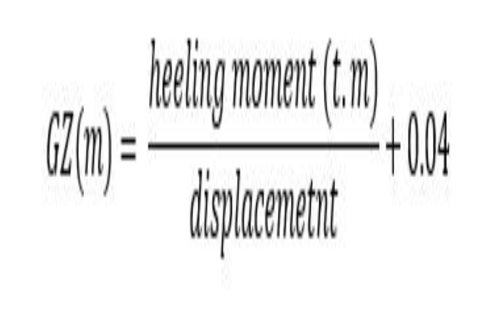
(c) a residual righting lever (GZ) value, is to be obtained within the range specified in subparagraph (1)(a), when determined by the formula:
-
-
-
where the heeling moment is to be taken as the greatest value resulting from any one of the following effects:
-
(i) the crowding of all passengers towards one side of the ship;
-
(ii) the launching of all fully loaded davit-launched survival craft on one side of the ship;
-
(iii)the pressure of the wind on one side of the ship;
-
where in no case shall the GZ value so determined be less than 0.10 metres:
-
(d) for the purpose of calculating the heeling moments in subparagraph (1)(c), the following assumptions shall be made:
-
(i) moments due to crowding of passengers:
-
(a) 4 persons per square metre;
-
(b) a mass of 75 kilogrammes for each passenger;
-
(c) passengers shall be distributed on available deck areas towards one side of the ship on the decks where muster stations are located and in such a way that they produce the most adverse heeling moment;
-
-
(ii) moments due to launching of all fully loaded davit-launched survival craft on one side:
-
(a) all lifeboats and rescue boats fitted on the side to which the ship has heeled after having sustained damage shall be assumed to be swung out fully loaded and ready for lowering;
-
(b) for lifeboats which are arranged to be launched fully loaded from the stowed position, the maximum heeling moment during launching should be taken;
-
(c) a fully loaded davit-launched liferaft attached to each davit on the side to which the ship has heeled after having sustained damage shall be assumed to be swung out ready for lowering;
-
(d) persons not in the life-saving appliances which are swung out shall not provide either additional heeling or righting moment;
-
(e) life-saving appliances on the side of the ship opposite to the side to which the ship has heeled shall be assumed to be in a stowed position;
-
-
(iii) moments due to wind pressure:
-
(a) a wind pressure of 120N/m2 to be applied;
-
(b) the area applicable shall be the projected lateral area of the ship above the waterline corresponding to the intact condition;
-
(c) the moment arm shall be the vertical distance from a point at one half of the mean draught corresponding to the intact condition to the centre of gravity of the lateral area;
-
-
-
(e) in intermediate stages of flooding, or during equalisation where applicable, the maximum righting lever shall be at least 0.05 metres and the range of positive righting levers shall be at least 7 degrees. In all cases only one breach in the hull and only one free surface need be assumed;
-
(2) The final condition of the ship after damage and, in the case of asymmetrical flooding, after equalisation measures have been taken shall be as follows:
-
(a) in the case of symmetrical flooding there shall be a positive residual metacentric height of at least 50 millimetres as calculated by the constant displacement method;
-
(b) in the case of asymmetrical flooding the angle of heel for one-compartment flooding shall not exceed 7 degrees. For the simultaneous flooding of two or more adjacent compartments a heel of 12 degrees may be permitted;
-
(c) in no case shall the margin line be submerged in the final stage of flooding.
-
-
At intermediate stages of flooding the margin line is not to be submerged unless partial subdivision above the bulkhead deck in accordance with regulation 11 limits sufficiently the spread of water along the bulkhead deck and results in an angle of heel not exceeding 15 degrees. In the case of ships carrying vehicles on the bulkhead deck, the angle of heel at intermediate stages of flooding shall not be greater than that which will submerge the margin line.
-
(3) For the purpose of the requirements in this section:
-
(a) when major progressive flooding occurs, that is, when it causes rapid reduction in the righting lever of 0.04 metres or more, the righting lever curve is to be considered as terminated at the angle at which the progressive flooding occurs, and the range and area referred to in subparagraphs (1)(a) and (b) should be measured to that angle; and
-
(b) in cases where the progressive flooding is of a limited nature that does not continue unabated and causes an acceptable slow reduction in righting lever of less than 0.04 metres, the remainder of this curve shall be partially truncated by assuming that the progressively flooded space is so flooded from the beginning.
-
-
Schedule 4
Construction of watertight bulkheads etc.
Strength and construction
-
1.
-
(1) Every bulkhead and other parts of the internal structure forming part of the watertight subdivision of the ship shall be of such strength and be so constructed as to be capable of supporting, with an adequate margin of resistance, the pressure due to the maximum head of water which it might have to sustain in the event of damage to the ship not being less than the pressure due to a head of water up to the margin line.
-
(2) Every such bulkhead and its parts shall be constructed of steel and:
-
(a) in the case of a ship which is classed with a Certifying Authority, and built to its survey requirements, it shall be sufficient for compliance with the requirements of subparagraph (1), if that Authority certifies that the watertight bulkheads and parts thereof are constructed in accordance with all the requirements of its Rules;
-
(b) in the case of a ship which is not classed with a Certifying Authority and built to the survey requirements of the Maritime and Coastguard Agency, compliance with subparagraph (1) will be met if the bulkhead scantlings comply with the appropriate rules of a Certifying Authority.
-
-
Watertight decks, steps and flats
- 2. The horizontal plating of decks, steps and flats required to be watertight shall be as strong as the bulkhead at the place where each occurs.
Watertight recesses and trunkways
- 3. Every recess and trunkway required to be watertight shall be so constructed as to provide strength and stiffness at all parts not less than that required for watertight bulkheads at a corresponding level.
Watertight tunnels
-
4. Every tunnel required to be watertight shall be constructed with plating of thickness not less than that required for bulkheads, other than the collision bulkhead. Initial tests of bulkheads, watertight and flats
-
5. All main watertight compartments are to be tested as follows:
-
(1) they should be filled with water or, alternatively, must be hose tested. The hose test must be carried out in the most advanced stage of the fitting out of the ship. In any case a thorough inspection of the watertight bulkheads shall be carried out;
-
(2) the forepeak, double bottom, duct keel and inner skin must be subjected to a head of water up to the margin line;
-
(3) tanks which are intended to hold liquids, and which form part of the subdivision of the ship, must be tested for tightness with water to a head up to the deepest subdivision load line, or up to a head corresponding to two-thirds of the depth from the keel to the margin line in way of the tanks, whichever is the greater, provided that in no case should the test head be less than 900 millimetres above the top of the tank.
-
Schedule 5
Subdivision load lines
-
Every ship shall be marked on its side amidships with the subdivision load lines assigned to it. The marks shall consist of horizontal lines 25 millimetres in breadth and 230 millimetres in length. The marks shall be painted in white or yellow if the background is dark or in black if the background is light and, if the sides of the ship are of metal, they shall be cut in, centre punched or indicated by welded beads; if the sides of the ship are of wood, the marks shall be cut into the planking to a depth of not less than 3 millimetres; if the sides are of other materials to which the foregoing methods of marking cannot effectively be applied, the marks shall be permanently affixed to the sides of the ship by bonding or some other effective method.
-
The subdivision load line shall be identified with the letter C and if there is more than one subdivision load line, the subdivision load lines shall be identified with the letter C and with consecutive letters beginning from the deepest subdivision load line, which shall be marked CA.
-
The identifying letters and numerals shall in every case be painted and cut in or centre punched or indicated by welded beads or otherwise marked as appropriate, on the sides of the ship in the same manner as the lines to which they relate.
Schedule 6
Bilge alarms, bilge pumps and bilge piping
Bilge alarms
-
1.
-
(1) A bilge alarm shall be fitted:
-
(a) in any watertight compartment containing propulsion machinery; and
-
(b) in any other compartment likely to accumulate bilge water, i.e. where a skin fitting is present, excluding void spaces, where the bilge level cannot be readily seen.
-
-
(2) To prevent pollution, compartments containing potential pollutants must not be fitted with auto-start bilge pumps.
-
(3) An auto-start bilge pump serving a clean compartment where a significant quantity of water could accumulate unnoticed, shall be fitted with an audible alarm at the control position(s). Should a number of such locations / alarms be present, then visual alarm indication must also be fitted to enable rapid location of the source of the alarm.
-
(4)The alarm shall provide an audible and visual warning at the control position.
-
-
Once activated the audible alarm shall continue to sound until it is acknowledged by positive action and shall not automatically cease sounding of its own accord.
Number and type of bilge pumps: ships of Class III
-
2. Every ship of Class III shall be provided with bilge pumps in accordance with the following table-
-
Number of Passengers ship is certified to carry Main engine pump * (number of pumps) Independent power pump (number of pumps) Emergency bilge pump (number of pumps) Hand Pump † (number of pumps) Up to 50 1 - - One for each compartment Over 50 up to 250 1 1 - One for each compartment Over 250 1 1 1 - - *The main engine pump may be replaced by one independent power pump.
-
† The hand pumps specified in this column may be replaced by an independent pump.
-
3. To every such ship for which an emergency bilge pump is specified, or in which a hand pump is replaced by an independent pump, such pumps shall be arranged as follows:
-
(1) one of the pumps shall be an efficient emergency pump of a submersible type having its source of power and the necessary controls situated above the ship’s bulkhead deck. Such pump and its source of power shall not be installed forward of the collision bulkhead or nearer to the side of the ship than one-fifth of the breadth of the ship measured at right angles to the centre line of the ship at the level of the deepest subdivision load waterline; or
-
(2) the power pumps in the ship and their sources of power shall be so disposed throughout the ship’s length that under any condition of flooding which the ship is required to withstand at least one such pump in an undamaged watertight compartment will be available.
-
Number and type of bilge pumps etc in ships of Classes IV to VI(A) inclusive
-
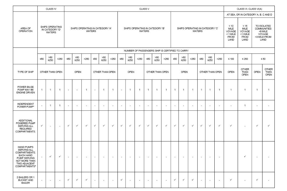
4. Every ship of Classes IV, V, VI and VI(A) shall be provided with bilge pumps and means of bailing in accordance with the following table and sections (1) – (3).
-
(1)The intent of these requirements is that for vessels with engine driven pumps that the failure of the main propelling machinery shall not prevent bilge pumping by mechanical means and that all compartments in such vessels except for those in (2) should be capable of being drained by two powered pumps drawing power from independent sources.
-
(2) Small compartments which are not likely to accumulate water, such as forepeaks, may be served by manual hand pumps. Powered bilge pumps must serve the following:
-
(i) any watertight compartment containing propulsion machinery; and
-
(ii) any other compartment likely to accumulate bilge water, i.e. where a skin fitting is present, excluding void spaces, where the bilge level cannot be readily seen.
-
-
(3)The second means of powered pumping must be powered from a source independent of the main engine pump. This may be achieved by individual submersible type pumps or other means such as a portable pump.
-
-
*The additional independent power pump and the hand pumps and additional powered pumps specified may be replaced by an independently powered pump providing paragraph 2 shall apply to such a ship as it applies to ships of Class III
-
5. Requirements for bilge pumps and bilge suctions
-
(1) Power bilge pumps shall, where practicable, be placed in separate watertight compartments and so arranged or situated as not to be readily flooded by the same damage, and if the machinery essential for propulsion is in two or more watertight compartments the bilge pumps there available shall be distributed between such compartments as far as possible.
-
(2) Every bilge pump provided shall be self-priming unless efficient means of priming are provided. Every such pump, other than pumps fitted as the additional powered pump, a hand pump or a pump provided for peak compartments only, shall, whether operated by hand or by power, be so arranged as to be capable of drawing water from any space required to be drained.
-
(3) Every independent power bilge pump shall be capable of giving a speed of water of not less than 2 metres per second through the ship’s main bilge pipe when its diameter is that determined by paragraph 6. Every such independent power bilge pump shall have a direct suction from the space in which it is situated, provided that not more than two direct suctions shall be required in one space. Every such suction shall be of a diameter not less than that of the ship’s main bilge pipe. The direct suctions in the ship’s machinery space shall be so arranged that water may be pumped from each side of the space through direct suctions to independent power bilge pumps.
-
(4) A main engine circulating pump shall be fitted with direct suction connections, which shall be provided with non-return valves, to the lowest drainage level in the ship’s machinery space, or as near thereto. Such connections in steamships shall be of a diameter at least two thirds of that of the main circulating pump inlet, and in motor ships of the same diameter as the main seawater circulating pump inlet. Where any main circulating pump is not suitable for this purpose, a direct emergency bilge suction shall be led from the largest available independent power-driven pump to the drainage level of the machinery space; the suction shall be of the same diameter as the main inlet of the pump used. The capacity of the pump so connected shall exceed that of a required bilge pump by a satisfactory amount. The open end of such suctions or the strainer, if any, attached thereto shall be accessible for clearing. The spindles of the ship’s main sea inlet and of the direct suction valves shall extend well above the engine room platform.
-
-
6. Arrangement of bilge pipes
-
(1)
-
(a) All bilge suction piping up to the connection to the pumps shall be independent of other piping.
-
(b) All bilge pipes used in or under fuel storage tanks or in boiler or machinery spaces, including spaces in which oil-settling tanks or oil fuel pumping units are situated, shall be of steel or other suitable material.
-
-
(2) Bilge suction pipes shall not be led through oil tanks except in the case of double bottom tanks. Where, in ships constructed on or after 1st September 1984 bilge suction pipes pass through deep ballast water tanks, such pipes should be of heavy gauge and the number of pipe joints kept to a minimum. The pipes shall be led above the line of the double bottom.
-
-
Additional requirements for ships constructed on or after 1st September 1984
- (3) The bilge pumping arrangements for cargo spaces containing flammable or toxic liquids shall be designed so that inadvertent pumping of such liquids through the main bilge system or any other system connected to a pump located in a machinery space can be prevented. Additional means of draining such cargo spaces shall be provided if this is found to be necessary when taking into consideration the quantity and characteristics of the liquids and their location.
-
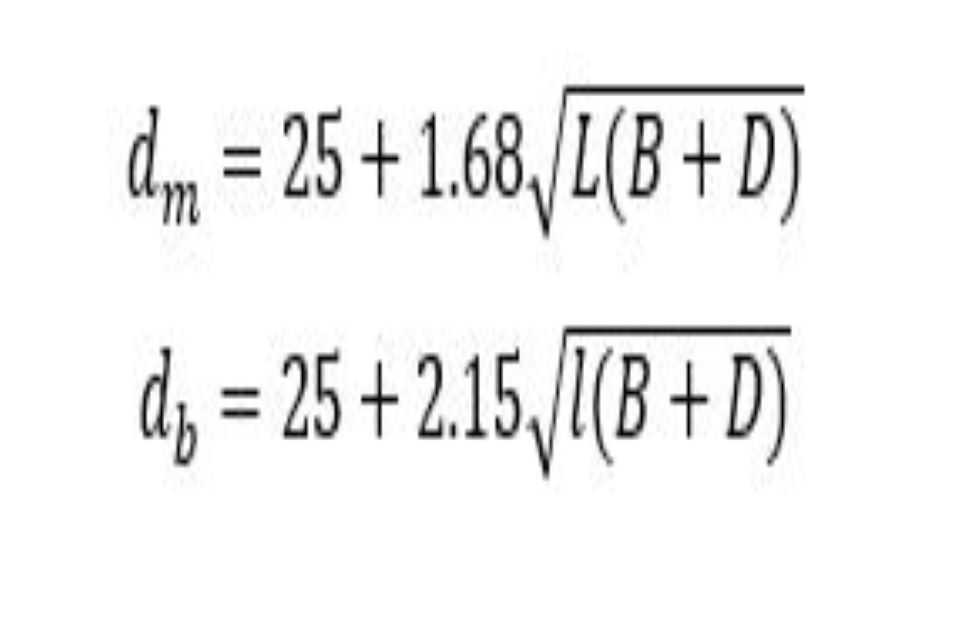
7. Diameter of bilge suction pipes
- (1) In every ship the internal diameter of main and branch bilge suction pipes shall be determined to the nearest size calculated according to the following formulae:
-
Where:
-
dm is the internal diameter of the main bilge suction pipes in millimetres;
-
db is the internal diameter of the branch bilge suction pipes in millimetres;
-
L is the length of ship in metres measured between perpendiculars taken at extremities of the deepest subdivision load waterline;
-
B is the greatest moulded breadth in metres at or below the ship’s deepest subdivsion load waterline;
-
D is the moulded depth of ship amidships at bulkhead in metres;
-
l is the length of compartment in metres.
-
-
*For ships constructed on or after 1st February 1992, ships the definition of “D” shall be as follows:
-
D = moulded depth of ship amidships at the bulkhead deck in metres; provided that, in a ship having an enclosed cargo space on the bulkhead deck which is internally drained in accordance with the requirements of paragraph 8 and which extends for the full length of the ship, D shall be measured to the next deck above the bulkhead deck. Where the enclosed cargo spaces cover a lesser length, D shall be taken as the moulded depth to the bulkhead deck plus lh/L, where l and h are the aggregate length and height respectively of the enclosed cargo space in metres.
-
8. Precautions against flooding through bilge pipes
-
(1) The bilge and ballast pumping systems shall be so arranged as to prevent water passing from the sea or from water ballast spaces into the ship’s cargo spaces or into any part of the machinery space or from one watertight compartment in the ship to another. The bilge connection to any pump which effects suction from the sea or from water ballast spaces shall be made by means of either a non-return valve or a cock which cannot be opened at the same time to the bilges and to the sea or to the bilges and the water ballast spaces.
-
(2) Provision shall be made to prevent the flooding of any watertight compartment served by a bilge suction pipe in the event of the pipe being severed or otherwise damaged in any watertight compartment through collision or grounding. Where any part of such pipe is situated nearer to the side of the ship than one-fifth of the breadth of the ship such a distance being measured at right angles to the centre line of the ship at the level of the deepest subdivision load waterline, or in any duct keel, a non-return valve shall be fitted to the pipe in the watertight compartment containing the open end of the pipe.
-
-
9. Drainage from cargo spaces
-
Requirements for ships constructed before 1st February 1992
- (1) In every ship which is marked with a summer load line, efficient drainage from any enclosed cargo space on the bulkhead deck shall be provided. Every discharge shall be in compliance with the requirements of subparagraph 2(2)(a) and (b) of Schedule 10 provided that where the freeboard to the bulkhead deck is such that the deck edge is immersed when the ship heels 5 degrees either way, other arrangements shall be provided to drain such spaces satisfactorily. Drainage need not be provided in any particular compartments of any ship if by reason of the size or internal subdivision of those spaces, the safety of the ship is not thereby impaired.
-
Requirements for ships constructed on or after 1st February 1992
-
(2)
-
(a) In every ship provision shall be made for the drainage of enclosed cargo spaces on the bulkhead deck; however the means of discharge may be dispensed with in any particular compartment of any ship if by reason of size or internal subdivision of those spaces the safety of the ship is not thereby impaired.
-
(b) Where the freeboard to the bulkhead deck is such that the deck edge is immersed when the ship heels more than 5 degrees, the drainage shall be by means of a sufficient number of scuppers of suitable size discharging directly overboard. Every discharge shall be in compliance with the requirements of subparagraphs 2(2)(a) and (b) or 3 of Schedule 10.
-
(c) Where the freeboard is such that the edge of the bulkhead deck is immersed when the ship heels 5 degrees or less, the drainage of the enclosed cargo spaces on the bulkhead deck shall be led to a suitable space, or spaces, of adequate capacity, having a high water level alarm and provided with suitable arrangements for discharge overboard. In addition it shall be ensured that -
-
(i) the number, size and disposition of the scuppers is such as to prevent unreasonable accumulation of free water;
-
(ii) the pumping arrangements shall take account of the requirements for any fixed pressure water-spraying fire-extinguishing system;
-
(iii) water contaminated with petrol or other dangerous substances is not drained to machinery spaces or other spaces where sources of ignition may be present; and
-
(iv) where the enclosed cargo space is protected by a carbon dioxide fire extinguishing system the deck scuppers are fitted with means to prevent the escape of the smothering gas.
-
-
-
-
10. Bilge valves and cocks
-
(1) All distribution boxes, valves and cocks fitted in connection with the bilge pumping arrangements shall be in positions which are accessible at all times in ordinary circumstances and shall be so arranged that in the event of flooding, one of the bilge pumps may operate on any watertight compartment in the ship. If in any such ship there is only one system of pipes common to all such pumps, the necessary valves or cocks for controlling the bilge suctions shall be capable of being operated from above the ship’s bulkhead deck. If an emergency bilge pumping system is provided in addition to the main bilge pumping system it shall be independent of the main system and shall be so arranged that a pump is capable of being operated on any watertight compartment under flooding conditions; in that case the cocks and the valves necessary for the operation of the emergency system shall be capable of being operated from above the bulkhead deck.
-
(2) Every valve or cock which is required by this Schedule to be operated from above the bulkhead deck shall have its control at its place of operation clearly marked to show the purpose it serves and how it may be opened and closed and shall be provided with a means to indicate when it is open and when it is closed.
-
Schedule 7
Emergency and transitional source of eletrical power and emergency switchboards
This Schedule applies to ships of Class III constructed on or after 1st September 1984
-
1. The emergency source of electrical power, the associated transforming equipment, any transitional source of emergency electrical power required by paragraph 6, the emergency switchboard and the emergency lighting switchboard shall all be:
-
(1) located above the uppermost continuous deck;
-
(2) readily accessible from the open deck;
-
(3) located aft of the collision bulkhead or its extension above the bulkhead deck when fitted above that deck; and
-
(4) so located that a fire or other casualty in the spaces containing the main source of electrical power, the associated transforming equipment, the main switchboard or in any machinery space of Category A will not interfere with the supply, control, and distribution of emergency electrical supplies.
-
-
2. The emergency generating set may be used to supply services other than emergency supplies exceptionally for short periods provided that the independent operation of the emergency source of electrical power is safeguarded in all circumstances.
-
3. Discharge of accumulator batteries that constitute either the emergency source of electrical power or transitional source of electrical power shall be indicated on the main switchboard or in the machinery control room.
-
4. The emergency switchboard shall be supplied during normal operation from the main switchboard by an interconnector feeder which shall be adequately protected at the main switchboard against overload and short circuit; and in the case of a ship constructed on or after 1st September 1984:
-
(1) disconnected automatically at the emergency switchboard upon the failure of the main source of electrical power; and
-
(2) be at least protected against short circuit at the emergency switchboard if the system is arranged for the main switchboard to be supplied from the emergency switchboard.
-
-
5. In ships constructed on or after 1st September 1984 arrangements shall be made to disconnect nonemergency circuits from the emergency switchboard automatically, if necessary, to ensure that electric power is available for the required emergency supplies.
-
6. Starting arrangements for emergency generating sets
-
Requirements for ships constructed on or after 1st September 1984
-
(1) In every ship the emergency generating sets shall be capable of being readily started at a temperature of 0°C. If temperatures below 0°C are anticipated provision shall be made for heating the engine so that it will start readily.
-
(2) The starting, charging and energy storing devices provided, which shall not be used for any purpose other than the operation of the emergency generating set, shall be located in the emergency generating set space except that the air receiver of the emergency generating set may be supplied from the main or auxiliary compressed air system through a non-return valve installed in the emergency generating set space.
-
(3) The stored energy required for starting shall be maintained at all times:
-
(a) in electric and electro-hydraulic systems, from the emergency switchboard; and
-
(b) in compressed air systems, by the main or auxiliary compressed air system or by an emergency air compressor which, if it is electrically driven, shall be supplied from the emergency switchboard.
-
-
(4) The emergency generating set shall:
-
(a) be equipped with a starting system having sufficient stored energy for three consecutive starts; and
-
(b) be provided with an additional source of stored energy independent of the starting system required by subparagraph (a) capable of producing a further three starts within 30 minutes unless an alternative and independent starting system is provided or effective manual starting can be demonstrated.
-
-
Schedule 8
Storage and distribution of gaseous fuel
-
1. In every ship in which oil or gaseous fuel is used in engines or boilers for the propulsion or safety of the ship, the arrangements for the storage, distribution and utilisation of the fuel shall be such that the effective use of the engines can be maintained under all conditions likely to be met by the ship in service.
-
2. In every ship in which oil or gaseous fuel is used, the arrangements for the storage, distribution and utilisation of the fuel shall be such that, having regard to the hazard of fire and explosion which the use of such fuel may entail, the safety of the ship and of persons on board is preserved.
-
3. Every oil fuel installation which serves a boiler supplying steam for the propulsion of the ship shall include not less than two oil fuel units.
-
Ships constructed on or after 1st September 1984
-
4. In addition to complying with paragraphs 1 to 3 every ship constructed on or after 1st September 1984 shall comply also with paragraphs 5 and 6.
-
5. In every ship in which oil or gaseous fuel is used, the arrangements for storage, distribution and utilisation of fuel shall comply at least with the provisions of this paragraph.
-
(1)Oil fuel systems containing heated fuel oil at a pressure exceeding 180 kPa shall be in illuminated locations so that defects and leakage can be readily observed. Where it is impracticable to meet the requirements of this subparagraph the Certifying Authority may permit other arrangements.
-
(2) Oil fuel tanks shall be part of the ship’s structure and shall be located outside machinery spaces of Category A. When oil fuel tanks, except double bottom tanks, are necessarily located adjacent to or within machinery spaces of Category A at least one of their vertical sides shall be contiguous to the machinery space boundaries and, if practicable, they shall have a boundary common with the double bottom tanks. The area of the tank boundary common with the machinery space shall be kept to a minimum. Any oil fuel tank located within the boundaries of machinery spaces of Category A shall not contain fuel having a flash point of less than 60°C. Where it is impracticable to meet the requirements of this subparagraph, the Certifying Authority may permit other arrangements.
-
(3) Every oil fuel tank shall, where necessary, be provided with savealls or gutters which will catch any oil which may leak from the tank.
-
(4) Oil fuel tanks shall not be situated directly above boilers or other heated surfaces.
-
(5) Oil fuel shall not be carried in forepeak tanks.
-
(6) Means shall be provided for the removal of water from fuel oil. Such means shall include the fitting of water drain valves to daily service tanks, settling tanks and where practicable, to other oil fuel tanks. Where the removal of water by drain valves is impracticable water separators shall be fitted in the supply lines to propulsion machinery.
-
(7) Savealls or gutters and screens shall be provided to prevent oil fuel that may leak under pressure from any pump, filter or heater from coming into contact with boilers or other heated surfaces.
-
(8) Every pipe connected to any oil fuel storage, settling, or daily service tank, not being a double bottom tank, which if damaged would otherwise permit discharge of the contents so as to cause a fire hazard shall be fitted with a valve or cock which shall be secured to the tank to which it is connected and be capable of being closed from a readily accessible position outside the space in which the tank is situated provided that in the case of any inlet pipe to such a tank, a non-return valve similarly secured to the tank may be substituted. In the case of an oil fuel deep tank traversed by any shaft or pipe tunnel, in addition to the valve or cock secured to the tank, a valve or valves may be fitted on the pipe line or lines outside the tunnel or tunnels to enable control to be exercised in the event of fire.
-
(9) Provision shall be made which will prevent overpressure in any oil fuel tank, oil fuel filling pipe or any part of the oil fuel system. Air and overflow pipes and relief valves shall discharge to a position where there will be no risk of fire or explosion from the emergence of oil or oil vapour.
-
(10) Every oil fuel pipe shall be made of steel or other suitable material except that flexible pipes may be permitted in positions where the Certifying Authority is satisfied that they are necessary; such flexible pipes and their attachments shall be constructed to the satisfaction of the Certifying Authority.
-
-
6. Safe and efficient means of ascertaining the amount of oil fuel contained in any oil fuel tank shall be provided. Sounding pipes shall not terminate in any space where the risk of ignition of spillage therefrom could arise. In particular, sounding pipes shall not terminate in passenger spaces or crew spaces. Other means of ascertaining the amount of oil fuel may be permitted provided that the failure of such means or overfilling of the tanks will not permit release of oil fuel.
-
Ships constructed on or after 1st February 1992
-
7. In the case of ships constructed on or after 1st February 1992, sounding pipes shall not terminate in machinery spaces. However, where the Certifying Authority considers that impracticable it may permit the termination of sounding pipes in machinery spaces on condition that:
-
(1) an oil level gauge is provided meeting the requirements of subparagraph (4);
-
(2) the sounding pipes terminate in locations remote from ignition hazards unless precautions are taken, such as the fitting of effective screens to prevent the oil fuel in the case of spillage through the terminations of the sounding pipes from coming into contact with a source of ignition;
-
(3) the terminations of sounding pipes are fitted with self-closing blanking devices and with a small diameter self-closing control cock located below the blanking device for the purpose of ascertaining before the blanking device is opened that oil fuel is not present. Provision shall be made so as to ensure that any spillage of oil through the control cock involves no ignition hazard;
-
(4) other oil level gauges may be used in place of sounding pipes. Such means, like the means provided in subparagraph 7(a), shall not require penetration below the top of the tank and their failure or over-filling of the tanks shall not permit release of fuel.
-
Lubricating and other Oil Systems
-
Ships constructed on or after 1st September 1984
-
8. Paragraphs 9 and 10 apply to ships constructed on or after 1st September 1984.
-
9. The arrangements for the storage, distribution and utilisation of lubricating oil in machinery spaces of Category A shall comply with the requirements of subparagraphs 5(1), 5(4), 5(7), 5(8), 5(9), 5(10), 6 and 7 as applicable as they apply to oil fuel installations except that tank gauges of the flat glass type, provided with self-closing valves at each tank connection and sight flow glasses having an acceptable degree of fire resistance may be permitted. Alternative arrangements may be permitted in machinery spaces other than machinery spaces of Category A where the Certifying Authority is satisfied that the safety of the ship is not impaired.
-
10. The arrangements for the storage, distribution and utilisation of flammable oils, other than fuel and lubricating oil, used in power transmission control and activating systems and heating systems shall be such as to ensure the safety of the ship and persons on board. In enclosed spaces containing a source of ignition the arrangements shall comply with subparagraphs 5(4), 5(7), 5(9), 5(10), 6 and 7 as they apply to oil fuel installations except that tank gauges of the flat glass type provided with self closing valves at each tank connection may be permitted.
Arrangements for oil fuel, lubricating oil and other flammable oils
-
11. Ships constructed before 1st July 1998 shall comply with the requirements of paragraphs 12, 13 and 14 not later than 1st July 2003, except that a suitable enclosure on engines having an output of 375 kW or less having fuel injection pumps serving more than one injector may be used as an alternative to the jacketed piping system in paragraph 12.
-
12. All external high pressure fuel delivery lines between the high-pressure fuel pumps and fuel injectors shall be protected with a jacketed piping system capable of containing fuel from a high-pressure line failure. A jacketed pipe incorporates an outer pipe into which the high-pressure fuel pipe is placed forming a permanent assembly. The jacketed piping system shall include a means for collection of leakages and arrangements shall be provided for an alarm to be given of a fuel line failure.
-
13. All surfaces with temperatures above 220°C which may be impinged as a result of a fuel system failure shall be properly insulated.
-
14. Oil fuel lines shall be screened or otherwise suitably protected to avoid as far as practicable oil spray or oil leakages onto hot surfaces, into machinery air intakes, or other sources of ignition. The number of joints in such piping systems shall be kept to a minimum.
Schedule 9
Steering gears
-
Requirements for ships constructed before 1st September 1984</b?
-
1. Every ship shall be provided with an efficient main and auxiliary steering gear. Provided that if the main steering gear power units and their connections are fitted in duplicate and each power unit enables the steering gear to meet the requirements of subparagraph 2(2) no auxiliary steering gear shall be required.
-
2. In every such ship:
-
(1) the main steering gear shall be of adequate strength and sufficient to steer the ship at maximum service speed. The main steering gear, including the rudder and associated fittings, and rudder stock shall be so designed that they are not damaged at maximum astern speed;
-
(2) the main steering gear shall be capable of putting the rudder over from 35 degrees on one side to 35 degrees on the other side with the ship running ahead at maximum service speed. The rudder shall be capable of being put over from 35 degrees on either side to 30 degrees on the other side in not more than 28 seconds at maximum service speed; and
-
(3) the auxiliary steering gear shall be capable of being rapidly brought into action and shall be of adequate strength and of sufficient power to enable the ship to be steered at navigable speed and, in any such ship in which a rudder stock of over 228.6 millimetres diameter in way of the tiller is required to comply with subparagraph (1), the auxiliary steering gear shall be operated by power.
-
-
3.
-
(1) In every such ship in which a rudder stock of over 228.6 millimetres is required to comply with subparagraph 2(2), there shall be provided a suitably located alternative steering station. In every other ship means shall be provided by which the ship can be steered from a position aft.
-
(2) In every such ship the remote steering control systems from the principal and alternative steering stations shall be so arranged that failure of either system will not result in inability to steer the ship by means of the other system. Means of communications shall be provided to enable orders to be transmitted from the bridge to the alternative steering station.
-
-
4. In every such ship which is fitted with power operated steering gear the position of the rudder shall be indicated at the principal steering station.
-
Requirements for ships constructed on or after 1st September 1984
-
5. Every ship shall be provided with an efficient main steering gear and, subject to paragraph 12 an efficient auxiliary steering gear. The main steering gear and the auxiliary steering gear shall be arranged so that the failure of one of them will not render the other one inoperative. Means of communication shall be provided to enable orders to be transmitted from the bridge to any alternative steering station. In every ship which is fitted with power operated steering gear the position of the rudder shall be indicated at the principal steering station.
-
6. The steering gear components, the rudder stock, the rudder and associated fittings shall be of sound and reliable construction. In particular, single essential components such as tillers and hunting gear shall be designed and constructed to withstand, with an adequate factor of safety, the maximum working stresses to which they may be subjected. Any bearings for such essential components shall be of a suitable type which shall be permanently lubricated or provided with lubrication fittings.
-
7.
-
(1) The design pressure for steering gear components and piping subject to internal hydraulic pressure shall be at least 1.25 times the maximum working pressure anticipated when the steering gear is operating taking into account any pressure which may exist in the low pressure side of the system. Fatigue criteria, taking into account pulsating pressure due to dynamic loads, shall be taken into account in the design of piping and components if appropriate; and
-
(2) relief valves shall be fitted to any part of the hydraulic system which can be isolated and in which pressure can be generated from a power unit or from external forces. The pressure at which relief valves operate shall not exceed the design pressure. The valves shall be of adequate size so as to avoid an undue rise in pressure above the design pressure.
-
-
8. Steering gears other than of the hydraulic type shall achieve equivalent standards to those required by this Schedule.
-
9. The main steering gear and rudder stock shall:
-
(1) be of adequate strength and sufficient to steer the ship at maximum ahead service speed;
-
(2) be capable of putting the rudder over from 35 degrees on one side to 35 degrees on the other side with the ship running ahead at maximum service speed and, under the same conditions, from 35 degrees on either side to 30 degrees on the other side in not more than 28 seconds;
-
(3) be operated by power if necessary to meet the requirements of subparagraph (2) and in any case in which the diameter of the rudder stock in way of the tiller is required to be greater than 120 millimetres excluding additional strengthening for navigation in ice; and
-
(4) be designed so that they will not be damaged at maximum astern speed.
-
-
10. The auxiliary steering gear shall:
-
(1) be of adequate strength and capable of being brought speedily into action in an emergency;
-
(2) be operated by power if necessary to meet the requirements of subparagraph (3) and in any case in which the diameter of the rudder stock in way of the tiller is required to be greater than 230 millimetres diameter excluding additional strengthening for ice; and
-
(3) be capable of putting the rudder over from 15 degrees on one side to 15 degrees on the other side in not more than 60 seconds with the ship at its deepest permitted draught and running ahead at one half of the maximum ahead service speed or 7 knots, whichever is greater.
-
-
11. Main and auxiliary steering gear power units shall where practicable:
-
(1) be arranged to re-start automatically when power is restored after a power failure;
-
(2) be capable of being brought into operation from a position on the navigating bridge; and
-
(3) be provided with an audible and visual alarm on the navigating bridge that will operate in the event of a power failure to any steering gear power unit.
-
-
12. An auxiliary steering gear need not be fitted if:
-
(1) two or more identical gear power units are fitted and which in the event of failure of any one of these units the remaining units are capable of operating the rudder in accordance with the requirements of paragraph 9(2); and
-
(2) the main steering gear is so arranged that after a single failure in its piping system or in one of the power units the defect can be isolated so that steering capability can be maintained or speedily regained. A steering gear with a proven record of reliability that does not comply with this subparagraph may be accepted on any ship the keel of which is laid, or which is at a similar stage of construction before 1st September 1986 or on a cargo ship which is converted to a passenger ship before that date.
-
-
13.
-
(1) Main steering gear control shall be provided on the navigating bridge and in the steering gear compartment. Two independent control systems operable from the navigating bridge shall be provided for a steering gear arranged in accordance with paragraph 10 except that when the control system consists of a hydraulic telemotor, a second independent system need not be fitted. The steering wheel or steering lever need not be duplicated.
-
(2) Auxiliary steering gear control shall be provided on the navigating bridge and in the steering gear compartment. Any auxiliary steering gear control system provided on the navigating bridge shall be independent of the control system for the main steering gear.
-
Electric and electro-hydraulic steering gear
-
14. Every ship which is fitted with electric or electro-hydraulic steering gear shall be provided with indicators which will show when the power units of such steering gear are running. These indicators shall be situated in the machinery control room or in such other position or positions as may be approved and on the navigating bridge.
-
15. Every such steering gear shall:
-
(1) be served by at least two exclusive circuits fed from the main switchboard one of which may pass through the emergency switchboard where provided; each circuit shall have adequate capacity for supplying all the motors which are normally connected to it and which operate simultaneously, and if transfer arrangements are provided in the steering gear compartment to permit either circuit to supply any motor or combination of motors, the capacity of each circuit shall be adequate for the most severe load condition; the circuits shall be separated as widely as is practicable throughout their length; an auxiliary electric or electro-hydraulic steering gear may be connected to one of the circuits supplying the main steering gear; and
-
(2) be provided with short circuit protection and an overload alarm for the protection of the circuits and motors; any protection provided against excess current shall be capable of conducting at least twice the full load current of the motor or motors taking into consideration the motor starting currents; where a three phase supply is used an alarm shall be provided that will indicate the failure of any one of the supply phases; the alarms required by this subparagraph shall be both audible and visual and located in a conspicuous position in the main machinery space or in the control room from which the main machinery is normally controlled.
-
Schedule 10
Openinings in the shell plating below the bulkhead deck
-
1. Sidescuttles
-
(1) Sidescuttles below the bulkhead deck shall be of a non-opening type and constructed to a recognised standard except that in ships constructed before 1st September 1984 opening type sidescuttles may be fitted, provided they have satisfactory locking arrangements.
-
(2)
-
(a) In every ship which is marked with a summer load line no sidescuttle shall be fitted in a between-decks such that its sill will be below a line drawn parallel to the freeboard deck at its side which has its lowest point either:
-
(ii) at a distance equal to 2.5 per cent of the breadth of the ship measured vertically above the summer load waterline; or
-
(ii) 500 millimetres above the summer load waterline;
-
whichever is the greater.
-
-
(b) In every ship which is not marked with a summer load line no sidescuttle shall be fitted in a between-decks such that its sill will be below a line drawn parallel to the bulkhead deck at its side which has its lowest point at a distance equal to 2.5 per cent of the breadth of the ship measured vertically above the deepest load waterline, except that for ships of Classes IV, V and VI such distance shall be 150 millimetres, unless it is of a non-opening type. In ships constructed before 1st September 1984, if in a between-decks of such a ship all the sills of the sidescuttles are above the aforesaid line, every sidescuttle in that between-decks shall be either of a non-opening type or of an opening type fitted with approved locking arrangements. No sidescuttle shall be so fitted that its sill is below the deepest subdivision load water line.
-
-
(3) Each sidescuttle fitted below the margin line shall be fitted with an efficiently hinged deadlight permanently attached so that it can be readily and effectively closed and secured watertight. Efficient hinged inside deadlights so arranged that they can be easily and effectively closed and secured watertight shall be fitted to all sidescuttles except that, abaft one-eighth of the ship’s length from the forward perpendicular and above a line drawn parallel to the bulkhead deck at the ship’s side and having its lowest point at a height of 2.5 per cent of the breadth of the ship above the deepest subdivision load line, the deadlights may be portable in passenger accommodation other than that for steerage passengers, unless the deadlights are required by the International Convention on Load Lines 1966 to be permanently attached in their proper positions. Such portable deadlights shall be stowed adjacent to the sidescuttles they serve.
-
(4) Sidescuttles shall not be fitted below the margin line to any space appropriated solely for the carriage of cargo. If sidescuttles are fitted below the margin line to spaces appropriated either to carry cargo or passengers, their deadlights shall be fitted with approved locking arrangements.
-
-
2. Inlets and discharges
-
(1) Each inlet and discharge led through the shell below the bulkhead deck shall be fitted with efficient and readily accessible means for preventing the accidental admission of water into the ship.
-
(2) Each discharge led through the shell from any space below the bulkhead deck, not being a discharge in connection with machinery, shall be provided with:
-
(a) one automatic non-return valve fitted at the shell of the ship and having positive means of closure from a position or positions above the bulkhead deck. Such positions shall be readily accessible at all times under service conditions. The means of closure shall be provided with an indicator showing whether the valve is open or closed; or
-
(b) two automatic non-return valves having no positive means of closure. The inboard valve shall, where practicable, be fitted above the deepest load waterline; where that is not practicable a locally controlled sluice valve interposed between the two automatic non-return valves shall be fitted; the inboard valve shall in every case be in such a position that it will at all times under service conditions be readily accessible for examination.
-
-
(3) The requirements of the International Convention on Load Lines 1966 shall apply to discharges led through the shell plating from spaces above the bulkhead deck.
-
(4) All valves attached to inlets or discharges, other than inlets or discharges connected with machinery, the failure of which may give rise to the danger of flooding, shall be made of steel, bronze or other equivalent material.
-
(5) Inlets and discharges connected with main or auxiliary machinery shall be fitted with cocks or valves between the pipes and the shell of the ship or between the pipes and a box attached to the shell. The controls to such cocks and valves or of any bilge injection system shall be readily accessible at all times under service conditions and fitted with indicators to show whether the cock or valve is open or closed. All valves attached to such inlets or discharges and all fittings outboard thereof shall be made of steel, bronze or other equivalent material. If made of steel, such valves shall be protected against corrosion.
-
(6) Discharge pipes led through the shell below the bulkhead deck of any ship of Class III shall not be fitted in a direct line between the outboard opening and the connection with a deck, water closet or other similar fitting, but shall be arranged with bends or elbows of substantial metal other than cast iron or lead.
-
-
3. Gangway and loading openings
-
(1) Each gangway port and cargo port fitted in the shell below the bulkhead deck shall be provided with a door or doors so fitted and designed as to ensure watertightness and structural integrity commensurate with the surrounding shell. They shall be effectively closed and secured watertight before the ship leaves port and shall be kept closed during navigation.
-
(2) In every ship which is marked with a summer load line no such gangway port or cargo port below the freeboard deck shall, unless otherwise permitted, be so situated that the lower edge of the port or opening will be below a line drawn parallel to the freeboard deck at side and having as its lowest point the waterline corresponding with the upper edge of the uppermost load line. In any ship which is not marked with a summer load line the lower edge of the port or opening shall in no case be below the deepest subdivision load waterline.
-