Radio frequency susceptibility test requirement (accessible)
Updated 22 June 2023

© Crown copyright 2023
This publication is licensed under the terms of the Open Government Licence v3.0 except where otherwise stated. To view this licence, visit nationalarchives.gov.uk/doc/open-government-licence/version/3 or write to the Information Policy Team, The National Archives, Kew, London TW9 4DU, or email: psi@nationalarchives.gov.uk.
Where we have identified any third party copyright information you will need to obtain permission from the copyright holders concerned.
This publication is available at https://www.gov.uk/government/publications/evidential-breath-alcohol-analysis-instrument/radio-frequency-susceptibility-test-requirement-accessible
First edition
CAST Publication number: 010/18
13 March 2018
The views expressed in this report are those of the authors, not necessarily those of the Home Office (nor do they represent Government policy).
1. Introduction
This test requirement applies only to electrical and electronic equipment where immunity to RF (radio frequency) interference is of principal importance. It supersedes all other RF susceptibility test requirements currently prescribed in Home Office Type Approval guides for evidential equipment.
Not only does the new requirement address the higher end of the frequency spectrum, where many transceiver-based devices now operate, but it also addresses the high probability of a number of these devices being active in close proximity inside the same vehicle. For this reason more stringent test limits are now applied.
Furthermore, the new requirement takes account of the changing landscape in frequency spectrum allocation, where constant improvement in transceiver technology coupled with an ever-increasing demand for bandwidth, drives liberalisation of spectrum in ways that have not been anticipated. For this reason susceptibility test levels are now uniformly applied throughout the entire frequency range.
Lastly, by aligning itself with existing commercial EMC (electromagnetic compatibility) standards, the new requirement aims to remove as much duplication as possible. By passing the UK Home Office’s Type Approval requirement for susceptibility, a product should automatically satisfy the CE-marking requirement for susceptibility.
2. Test philosophy
The new requirement places emphasis on the ‘WHAT’ and the ‘WHY’ of susceptibility testing, whilst leaving the ‘HOW’ to the vendor.
This means that the Home Office no longer prescribes how a product should be exercised and assessed during testing, but instead expects the vendor – as the ‘expert’ on its own product – to propose a test plan.
The test plan shall not only meet the test requirement, but shall also satisfy the Home Office that the vendor properly understands the risks and, where necessary, the mitigation measures to be employed.
Under no circumstances will the new test requirement exempt manufacturers or their agents from their obligation to comply with prevailing UK legislation, particularly regulations relating to electromagnetic compatibility and product safety.
3. Test plan
Before proceeding with any testing, the vendor needs to submit a test plan for approval by the designated Project Officer, who will assess the test plan and notify the vendor in writing as to whether the test plan has been approved or rejected.
If rejected or incomplete, the Project Officer will state the reason and allow the vendor to correct the test plan or to provide more information.
Once approved, the vendor will receive a written confirmation that the test plan meets the test requirements and that it may proceed with formal testing.
In order for the Project Officer to perform a proper assessment of the product and its test plan, he/she needs to have a clear understanding of how the various components connect and interact with one another. This requires a simple yet clear explanation, accompanied by annotated diagrams and comprehensive technical and operational documentation for the entirety of the product. Where any type of stimulator or simulator is used as part of the test method, its principle of operation needs to be illustrated and explained in detail.
Assessment will place particular focus on the evaluation and recommendation of:
- the directions required for appropriate RF exposure
- the dwell time required to suitably exercise the product
- the exercise method required to suitably simulate operational functionality
- the equipment and cable layout during testing
- any special conditions requiring additional or enhanced testing
It is, however, up to the vendor to explain, backed by technical evidence, how the product will be exercised and why, in his/her opinion, the selected exercise method and equipment layout is considered to be fully representative of a typical operational setting.
Equipment not capable of operating accurately and safely within the required levels must incorporate a mechanism to prevent the equipment from operating or to alert the operator to this fact. This mechanism shall be described in detail and the evidence to substantiate it shall be presented and agreed as part of the test plan.
Where a vendor believes that its equipment is likely to malfunction or incur damage as a result of enhanced field strength levels, satisfactory technical justification and evidence need to be produced for consideration by the Project Officer.
In addition to providing any existing EMC test reports and certifications, it will also be helpful if the vendor could make reference to other national and international markets where the product is currently being used.
Where equipment has already undergone EMC testing, the Project Officer will need to see the test plan, the test results and the accreditation of the test laboratory where testing was done. Upon assessing these documents, the Project Officer will decide what further testing needs to be performed.
Ultimately vendors are encouraged to develop and propose new, innovative and cost-effective ways of meeting the new EMC Type Approval requirements.
4. Test parameters
For ease of understanding, the new requirement is divided into three parts, a summary of which can be found in Annex 1 of this document.
4.1 Part 1 – Conducted susceptibility testing as part of CE-marking
This is taken from the CE-marking EMC test requirements and should therefore be performed in accordance with EN61000-4-6.
It covers conducted susceptibility induced by RF via cabling and it applies to all electrical and electronic equipment that have significant lengths of cabling attached during operational use. This usually applies to mobile or stationary equipment, irrespective of power source.
Level 3 of 10Vrms is applied over a frequency range of 150kHz to 80MHz stepping through at 1% frequency increments using 80% AM (amplitude modulation) at 1kHz.
4.2 Part 2 – Radiated susceptibility testing as part of CE-marking
This is taken from the CE-marking EMC test requirements and should therefore be performed in accordance with EN61000-4-3.
It covers radiated susceptibility and applies to all electrical and electronic equipment, whether handheld, mobile or stationary, and irrespective of cabling or power source.
A Class 4 level of 30V/m (peak of 54V/m when modulated) is applied over a frequency range of 80MHz to 6GHz stepping through at 1% frequency increments using modulation of 80% AM at 1kHz.
This differs only slightly from most implementations of CE-mark EMC testing in that:
- it covers the full frequency range up to 6GHz, as opposed to the commonly-used ranges up to 2GHz and 3GHz
- it uses the higher Class 4 (30V/m) level of RF field strength, as opposed to the commonly-used commercial and industrial levels of Class 2 (3V/m) and Class 3 (10V/m) respectively. Class 4 is defined as being appropriate for an environment where portable transceivers are used within 1m proximity.
- It necessitates thorough and overall RF exposure, meaning that in an attempt to ensure consistent field strength throughout the EUT (equipment under test), irradiation could be required from all six orthogonal directions. As this will increase the duration and cost of testing, other alternatives (for example the use of reverberation chambers as defined in standard EN61000-4-21) may be considered, provided that these alternatives are reliable, repeatable and generally recognised within the EMC community. In any event, alternative methods should be agreed with the Project Officer during the test plan phase.
4.3 Part 3 – Additional radiated susceptibility testing
The tests in Part 3 are in addition to those described in Parts 1 and 2, and unless otherwise stated, should also be performed in accordance with EN61000-4-3.
These tests cover radiated susceptibility and apply to all electrical and electronic equipment, whether handheld, mobile or stationary, and irrespective of cabling or power source.
The primary aim of Part 3 is to provide a higher degree of certainty by taking into account two factors that are likely to affect RF susceptibility:
- Increased RF field strength
Increased field strength levels can be the result of a number of things, amongst these being the presence of several RF transmitters operating simultaneously and in close proximity, or the use of RF transmitters near RF-reflecting surfaces.
-
Pulse-based amplitude modulation and access method
These types of modulations and access methods have been seen to expose susceptibility weaknesses not observed during use of the standard AM modulation prescribed in Part 2, which amongst others also covers technologies like UMTS and LTE. This could be attributed to the transient nature of the amplitude changes that occur in communication technologies like TETRA, GSM, DCS, Bluetooth, Zigbee and WiFi.
The special conditions in which the above-mentioned factors come into play, along with the enhanced test parameters required to expose them, are described in Annex 2 and Annex 3.
Part 3 also wishes to draw attention to the possibility of interference between radar TLEDs (traffic law enforcement devices) and vehicle-fitted SRR (short range radar) anti-collision systems, both operating within the 24GHz band. Annex 4 describes the testing that may be required for this type of equipment.
Not all tests in Part 3 necessarily apply to all products; however, tests deemed not applicable need to be agreed with the Project Officer during the test plan phase.
Annex 1: Summary of susceptibility test parameters
Part 1: Conducted susceptibility testing as part of CE-marking
Frequency band: 150kHz to 80MHz
Level: 10Vrms
Modulation: 80% AM at 1kHz
Steps: 1% frequency increments
Dwell time: To be agreed in test plan
RF exposure: Cable-induced
Exercise method: To be agreed in test plan
Part 2: Radiated susceptibility testing as part of CE-marking
Frequency band: 80MHz to 6GHz
Field strength: 30V/m (peak of 54V/m when modulated)
Modulation: 80% AM at 1kHz
Steps: 1% frequency increments
Dwell time: To be agreed in test plan
Antenna polarisation: Horizontal and vertical
Horizontally-rotated exposure: To be agreed in test plan
Vertically-rotated exposure: To be agreed in test plan
Exercise method: To be agreed in test plan
Part 3: Additional radiated susceptibility testing
a. TETRA
Frequency band: 380MHz to 424MHz
Field strength: 65V/m peak (see Annex 2 for exceptions)
Modulation: Pulse-based AM (see Annex 3 for setup)
Steps: 1% frequency increments
Dwell time: To be agreed in test plan
Antenna polarisation: Horizontal and vertical
Horizontally-rotated exposure: To be agreed in test plan
Vertically-rotated exposure: To be agreed in test plan
Exercise method: To be agreed in test plan
b. GSM, DCS, Bluetooth, Zigbee, WiFi
Frequency band: 868MHz to 2.5GHz and 5 to 6GHz
Field strength: 54V/m peak
Modulation: Pulse-based AM (see Annex 3 for setup)
Steps: 1% frequency increments
Dwell time: To be agreed in test plan
Antenna polarisation: Horizontal and vertical
Horizontally-rotated exposure: To be agreed in test plan
Vertically-rotated exposure: To be agreed in test plan
Exercise method: To be agreed in test plan
c. Short range radar
Frequency band: 24.15GHz
Field strength: 0.2V/m peak (see Annex 4 for guidance)
Modulation: CW (unmodulated carrier wave)
Dwell time: To be agreed in test plan
Antenna polarisation: To be agreed in test plan
RF exposure: Into TLED antenna
Exercise method: To be agreed in test plan
Annex 2: Field strength requirements for tetra in vehicles
Although Annex 1 Part 3a sets a susceptibility test level of 65V/m for equipment that will not be operated within 20cm of a TETRA transceiver, there are environments where this level does not adequately cover the levels measured during testing.
The interior of a typical vehicle is one such example, where studies have demonstrated a multiplicative effect on RF fields originating from transmitter antennas located inside the vehicle. This has led to the development of the more-stringent susceptibility requirements described below.
Any equipment operated inside a vehicle in which a TETRA transceiver, along with its antenna, is also present and switched ON, must meet the minimum susceptibility field strength requirements as prescribed in Table 1 below. It is, however, strongly advised that for general in-vehicle use, vendors design and test their equipment to at least the 160V/m level. As the presence of two TETRA handsets inside a vehicle is the most recurrent operational scenario, a level of 160V/m is likely to be specifically requested.
Table 1: TETRA field strength requirements within vehicles
| Circumstance | Applicable test | Field strength |
|---|---|---|
| For equipment to be used inside a vehicle, where the possibility exists that at least three TETRA handsets could be present inside the vehicle | Part 3a | 200V/m peak |
| For equipment to be used inside a vehicle, where no more than two TETRA handsets will be present inside the vehicle | Part 3a | 160V/m peak (recommended) |
| For equipment to be used inside a vehicle, where no more than one TETRA handset will be present inside the vehicle | Part 3a | 125V/m peak |
| For equipment to be used inside a vehicle, where only the vehicle- fitted TETRA radio with an externally-mounted antenna, will be present | Part 3a | 65V/m peak |
| For equipment that will never be used inside a vehicle, nor be used at a proximity of less than 20cm from any TETRA handset | Part 3a | 65V/m peak |
Annex 3: Bespoke test modulation for pulse-based technologies
Studies have shown pulse-based AM to be more disruptive to nearby electronic equipment than the traditional sine wave-based AM used in EMC susceptibility testing. For this reason, two bespoke modulation schemes are used – pseudo-TETRA and ED130-specified.
Pseudo-TETRA
This test modulation emulates typical TETRA modulation schemes and applies only to testing in the band 380 to 424MHz. It comprises an 18kHz square wave, repeated at 17Hz using a duty cycle of 50%. The carrier is modulated to a depth of >98%. This is illustrated in Diagram 1 below.
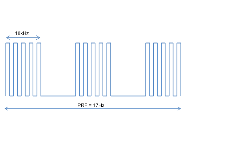
Diagram 1: Pseudo-TETRA test modulation
ED130-specified
This test modulation emulates typical TDMA-, CSMA- and FHSS-based modulation and access schemes used in technologies like GSM, DCS, Bluetooth, Zigbee and WiFi. It applies only to testing in the bands 868MHz –to 2.5GHz and 5 to 6GHz. It comprises an unmodulated square wave, repeated at 200Hz using a duty cycle of 12.5%. The carrier is modulated to a depth of >98%. This is illustrated in Diagram 2. Note: CDMA/FDMA-based technologies like UMTS and LTE are covered by the normal AM modulation scheme prescribed in Annex 1 Part 2.
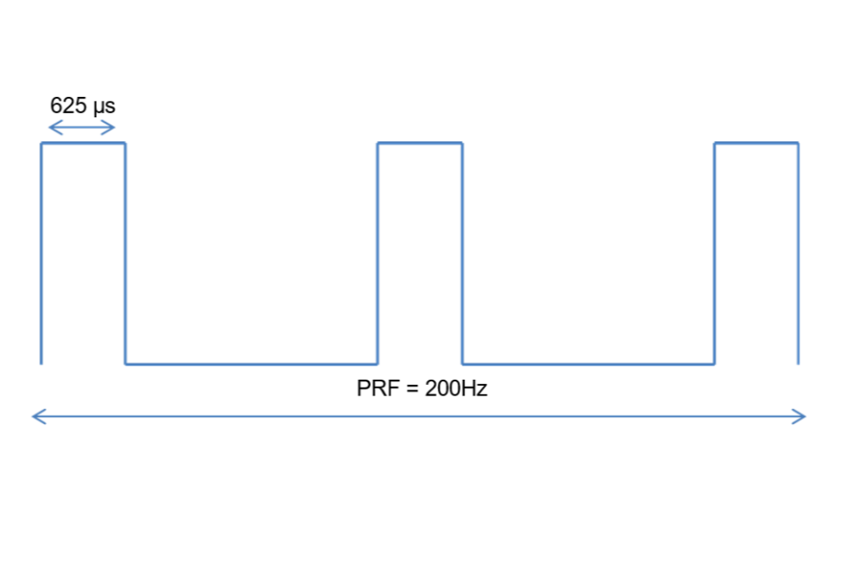
Diagram 2: ED130-specified test modulation
Annex 4: Radar traffic law enforcement devices
UK police radar speed TLEDs operate in the band 24.05 to 24.15GHz, whereas anti-collision radars in vehicles operate in the band 24.15 to 24.25GHz.
Although radar TLEDs are extremely unlikely to be affected by the low RF levels of these devices via ‘back door’ coupling (coupling not via the TLED’s antenna), the possibility of them being affected via ‘front door’ coupling (via the TLED’s antenna) is greater. As such, it is expected of vendors to ensure that radar equipment is sufficiently resilient against short range devices.
It is recommended that testing be conducted at 24.15GHz with the TLED antenna being irradiated by an unmodulated carrier wave with a field of 0.2V/m peak from a distance greater than 1m.